To facilitate removal of components mounted on the shaft of a pump that has been in service for a prolonged period, the
use of one of the better-know rust solvents is recommended. If this proves ineffective, the parts in question (not the shaft)
may be expanded by gradually heating up with a blow lamp.
This must be done evenly and very carefully, so that the shaft is kept as cool as possible, since heat deformation of a shaft
can never be fully remedied. This heating of the parts may be repeated as required, and force should never be used to remove
these parts, since this will lead to bending or scoring of the shaft.
Never use a hammer to drive off couplings, balance discs, stage casings, impellers, diffusers or spacer sleeves, as this
might damage these components. After completion of dismantling, the shaft should be checked for true running, particularly if it
was heated up during dismantling. Shafts used in pumps handling hot liquids can never be permanently straightened by
bending after they have been subjected to thermal stresses; they will deform again immediately they are exposed to heat. The
sealing faces require special care when dismantling the pump. They must be protected from damage, and ground faces should
be placed individually, seal face down, on clean wood or cardboard surfaces.
If dismantling reveals that the pump must be sent away for a major overhaul, it must be reassembled and properly mounted
on the bedplate before being despatched to our works.
5. 2. Reassembly
The individual components on the rotating assembly are numbered in sequence, starting at the suction end. Components which
belong together should always be reassembled together.
First of all, the rotating assembly, with new parts where required, is reassembled, or a complete replacement rotor is assembled, if
the old one is no longer serviceable, and is the checked for true running. The shaft should be coated with a suitable lubricant
(molybdenum disulphide or similar product), before slipping on the components, to prevent sticking and facilitate subsequent
dismantling. After the true running check, the rotor should be dynamically balanced, then dismantled again.
5.2.1. Reassembly of pump with O-ring seals
Reassembly takes place from the drive end.
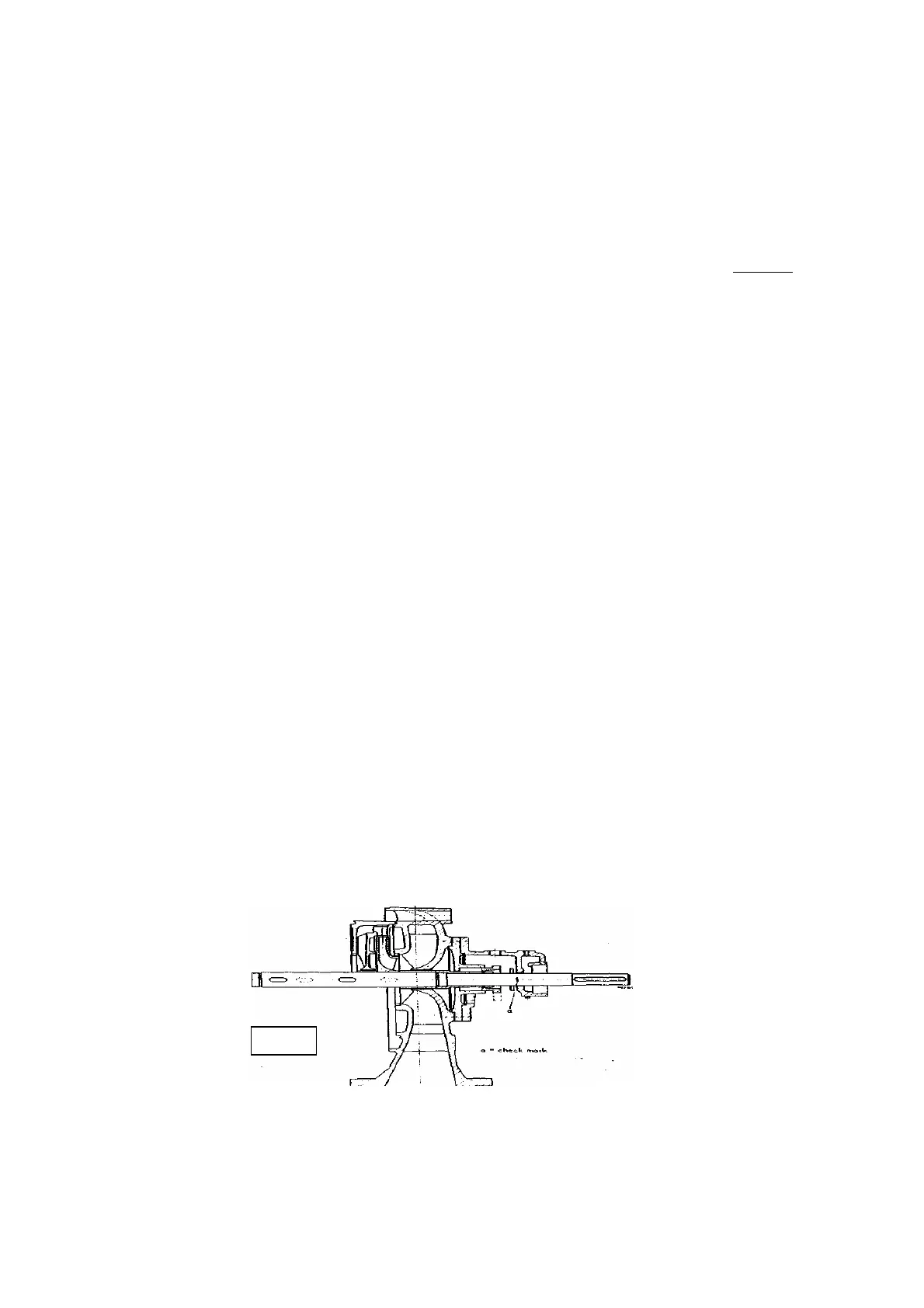
1. The empty stuffing box housing (4510) with gland (4520), the bearing bracket (3500) and the suction casing (1060) are bolted
together, and for convenience this partial assembly is best stood on the flange of the suction casing (fig. 20).
2. After the shaft protecting sleeve (5240.1) has been screwed on to the shaft, and the spacer sleeve (5251) slipped into position, the
shaft is inserted into the assembly, the flinger ring (5070) being positioned correctly between (4510) and (3500) .
3. The first impeller (2300) and diffuser (1710) are placed on the shaft, making sure that the centre line of the impeller outlet comes into
register with the centre line of the diffuser inlet see ( fig. 21).
Fig. 20
4. A check mark must now be scribed on the shaft at its exit from the bearing housing (fig. 20), so that the axial position of the rotor
assembly can later be checked ( fig. 21) after all the components have been mounted, and adjusted if necessary by machining the
hub of the balance disc (6020), or the spacer sleeve (5252) in the discharge casing ( if provided) .
- 22 -