4. Escape of water between the balance disc (6010) and
the shaft (2100).
Replace the parts damaged by water erosion, and carefully grind
all end faces absolutely flat; tighten the shaft protecting sleeve
very tightly.
5. Vapour formation inside the pump. Check the suction head. Vapour formation can arise if the pump
is overloaded or if the by-pass non-return valve fails, i.e. if the
by-pass orifice does not open promptly when the pump capacity
drops (the valve cone may stick in the top position). Vapour
formation can also arise as a result of sudden temperature or
pressure fluctuations in the suction vessel. Check that the
operating conditions as specified.
6. Escape of water between balance disc seat (6020)
and discharge casing (1070).
Renew the gasket and touch up the components damaged by
erosion, or renew them if necessary.
5. Dismantling and reassembling the pump
5. 1. Dismantling
Dismantling to check the pump internals and fit replacements parts should only be carried out by skilled personal or by one
of our own expect fitters.
The instruction in para 5.1 and 5.2.1 apply to pump with conventional stuffing boxes and anti-friction bearings as illustrated
in fig.24; if the pump has special the seals of plain bearings, the procedure should be modified to accord with the relevant
sectional drawing. Dismantling is begun from the discharge end, after disconnection all piping and uncoupling the driver.
Proceed as follow :
1. Remove bearing cover plate (3610) and roller bearing (3220).
2. Remove discharge end bearing bracket (3500) and stuffing box housing (4510) with gland (4520).
3. Unscrew shaft protecting sleeve (5240.2).
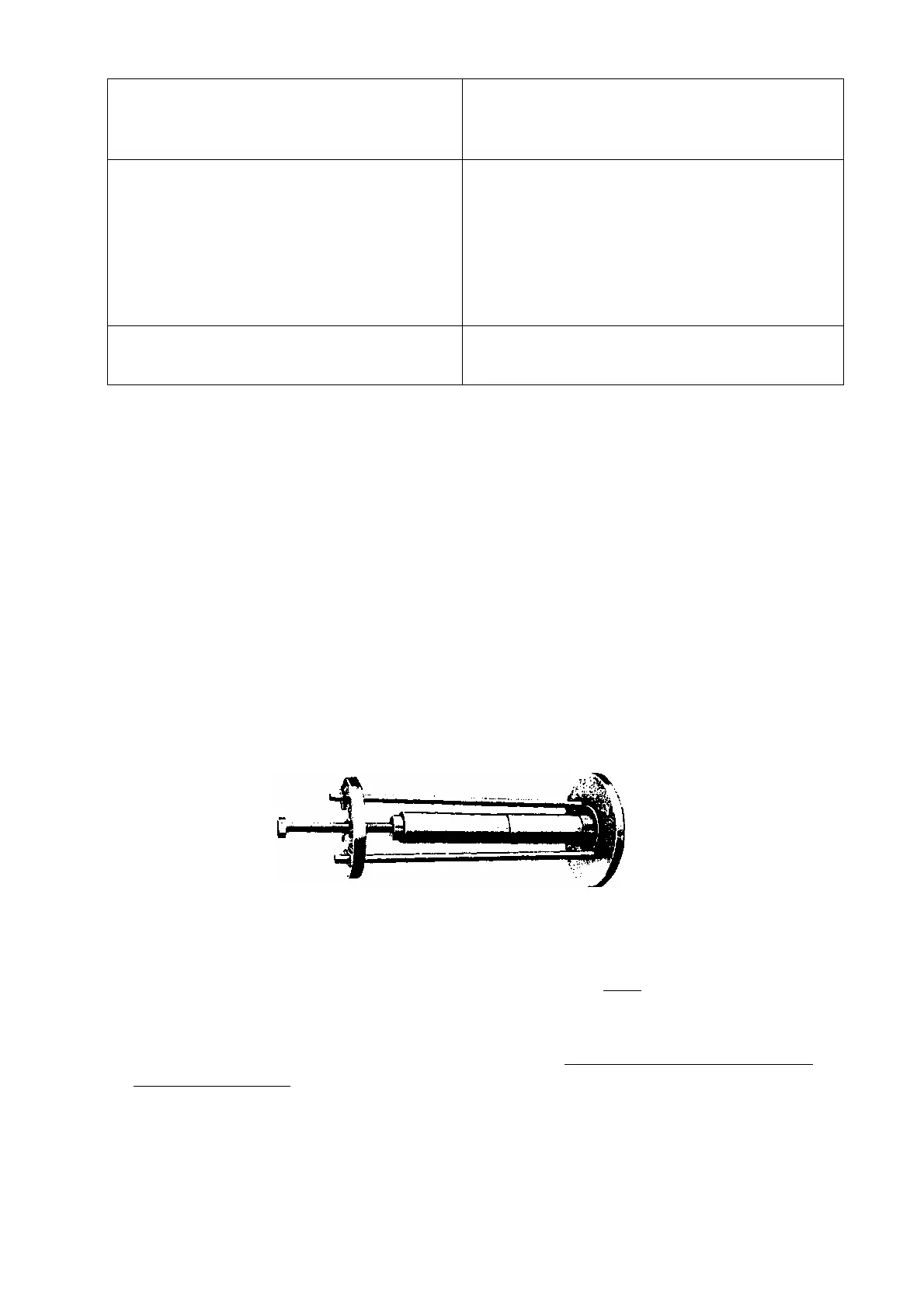
4. Withdraw balance disc (6010) by means of the extractor illustrated in fig. 19.
Fig. 19 Withdrawing the balance disc.
In MML pump sizes 150-350, the balance disc (6010) and the spacer sleeve (5252) in the discharge casing are separate
components, but share the same key on the shaft. This key must always be removed before the sleeve (5252) is withdrawn.
5. Dismantle the sheet steel cladding of the pump, remove the lagging and take off nuts (9201.1) of tie bolts (9050).
The stage casings (1080) should be underpinned before dismantling proceeds any further, to prevent them collapsing when
the discharge casing (1070) is removed.
6. Withdraw discharge casing (1070) and diffuser (1711).
7. Pull of the impellers (2300), stage casings (1080) with their diffusers (1710) and spacer sleeves (5210) for each stage,
from the shaft.
8. Finally dismantle the bearing bracket (3500) and the stuffing box housing (4510)
- 21 -