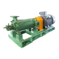
5. The first stage casing (1080) with inserted diffuser (1710) and O-ring (4120.5) are then scaled in the casing (1060). They are to be
well tapped in with a wooden or rubber mallet ( not a metal hammer ), and the stage casing must be suitably underpinned.
6. After the next impeller and spacer sleeve (5210) have been placed on the shaft, the second stage casing with its diffuser and O-ring
are tapped into position, as was done with the previous stage.
7. After mounting the last impeller, and, in the case of pomp sizes MML 150-350, the spacer sleeve on the discharge side, the
discharge cover (1070) with diffuser (1711) of final stage and the last O-rings (4120.5,4120.6) are fitted.
8. The tiebolts (9050)are then inserted, and the nuts (9201.1) lightly tightened on the cross.
9. The balance disc seat (6020) is carefully placed in position (do not forget gasket) and the balance disc (6010) is then slid onto the
shaft (2100). True running of the balancing device can be ensured by making a "blue" test with marking fluid, and touching up the
running faces if necessary.
10. The discharge end shaft protecting sleeve (5240.2) is then screwed firmly onto the shaft. At this stage of assembly, the rotor must
be able to slide easily in the axial direction.
11. The discharge end bearing bracket and the empty stuffing box housing with its gland are now bolted in position, the nuts being
tightened evenly on the cross. The flinger ring (5070) must not be overlooked.
12. The bearings (3220) end the bearing end covers (3600,3610) are then mounted. Verify that the rotor can be turned easily by hand.
13. Finally check that the shaft is correctly positioned. This is the case when the balance disc (6010) is in contact with the balance disc
seat (6020) and at the same time the control mark scribed on the shaft is in its original position in relation to the bearing housing.
14. If this is so, the stuffing box can now be packed as described in section 4. 4. 2.
15. Finally, connect the suction and discharge piping, and also the balance water line.
Before the pump is put into service, check the smooth rotation of the shaft, to make sure that the casing has not been distorted by
the piping. See also section 4. 4. for bearing lubrication.
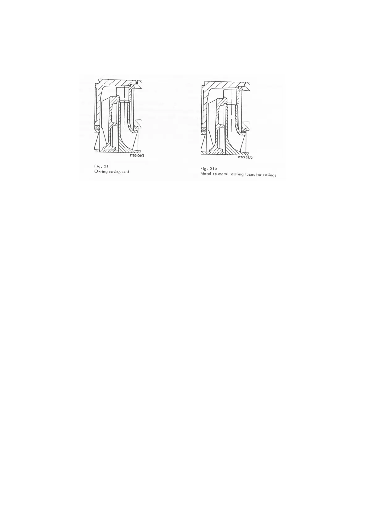
5.2.2. Reassembly of pumps with metal to metal sealing faces (Fig. 21a) .
Proceed as described in section 5.2.1. with the necessary modifications. The highest degree of cleanliness should be observed
during assembly of the mating parts. Before assembly is commenced, all the mating faces must be carefully examined. Should they not
be perfectly smooth and true, they must be ground manually by means of special cast iron grinding blocks (Figs. 22 and 23).
It is advisable to order these blocks when laying in a stock of spare parts.
Regrinding a sealing face by using the corresponding mating face as a grinding block, e. g. grinding two pump stage casings
againts one another, must be avoided at all costs, since the spigot and recess ( centering ) would be opened out there by.
- 23 -