2.2. Driver
The driver is usually coupled to the suction end of the pump. Pump rotation is clock-wise viewed from driver. On special
request, the pump can be supplied with the stub shaft at the discharge end (in this case, rotation is anti-clockwise viewed from
driver) or with stub shafts at both ends. The variety of drivers which can be used is so great that it would be impossible to
describe them all in the context of this booklet; therefore we refer you to the operating instruction manual supplied by the
manufacturer of the driver.
2.3. Made of operation of pump
The fluid flows through the suction casing (1060) at a given pressure, onto the first stage impeller (2300). A certain amount
of energy is imparted to the fluid in the impeller, which is provided with a number of vanes. The fluid then flows out of the
impeller into the diffuser (1710), where a partial conversion from kinetic energy into potential energy takes place, resulting in a
further increase in pressure. The return guides in the diffuser then lead the fluid onto the eye of the following impeller. This
process is repeated from stage to stage, and at each stage the pressure increases by the same amount, i. e. the stage head.
After leaving the final diffuser, the fluid penetrates into the discharge casing (1070) and thence into the discharge piping.
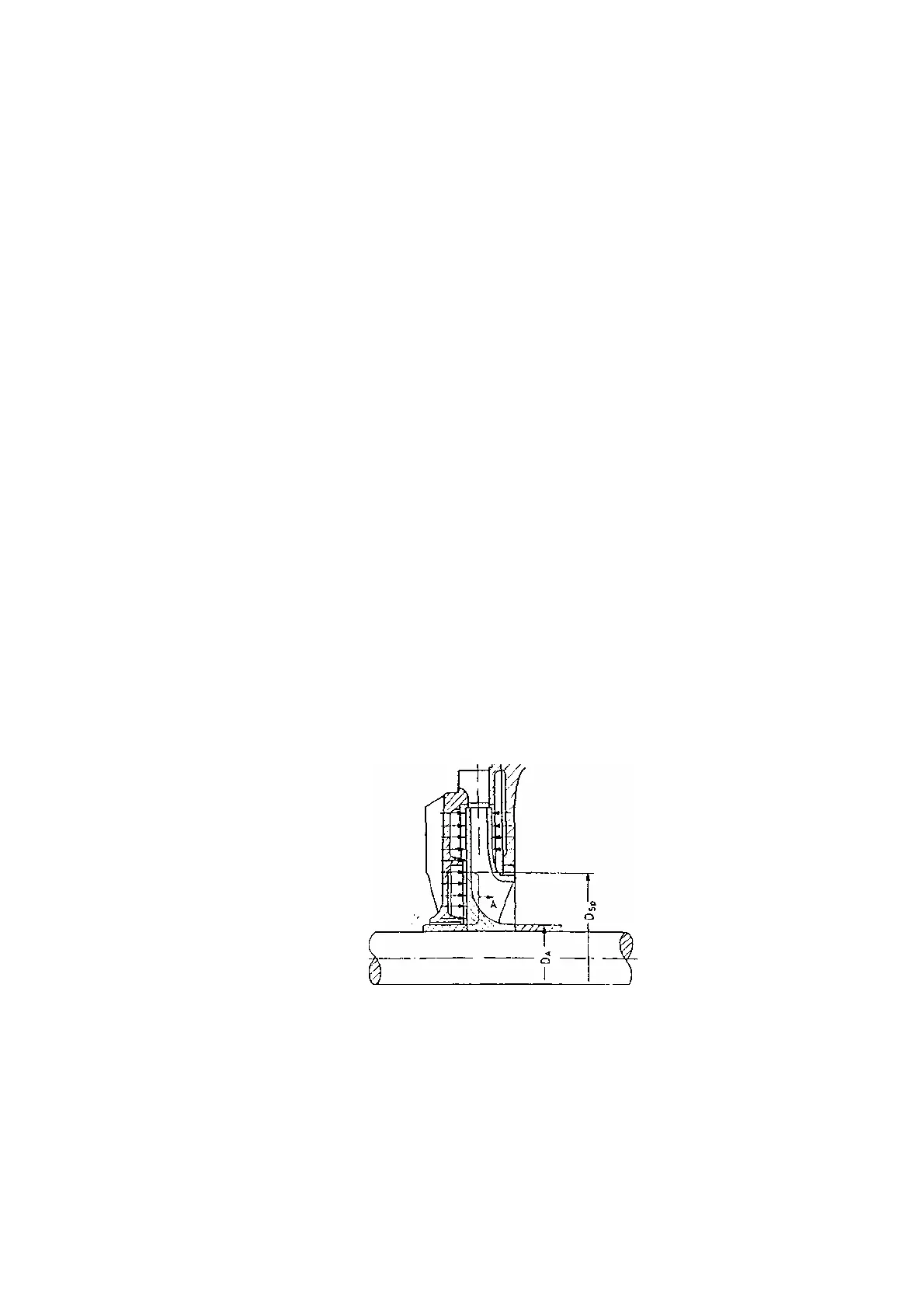
An axial thrust A ( see fig. 7 ) acts on every impeller; it is caused by the hydraulic pressure which acts on one side only of
the annulus with outside diameter Dςp (= seaIing clearance gap diameter) and inside diameter DA ( = o.d. of spacer sleeve).
This axial thrust A is transmitted to the rotor and is absorbed by a special hydraulic balancing device on MML series pumps.
This balancing device consists of a balance disc (6010) and a balance disc seat (6020), and it operates through the action of a
fixed area, or constant clearance gap (between the pump rotor and discharge casing) in series with a variable clearance gap
(between balance disc and balance disc seat). If, for instance, the variable clearance gap between balance disc and balance
disc seat is very narrow, this will result in a high pressure, equal almost to the full pump discharge pressure, acting on the
balance disc, and pushing the rotor axially towards the discharge end of the pump; the gap will consequently widen. If, on the
other hand, this gap is too wide, the increased flow of balance water which now flows through the balancing device will be
subjected to a greater pressure drop through the fixed area clearance gap, and consequently the thrust on the, balance disc will
decrease, causing the rotor to slide back towards the suction end of the pump. In operation, the rotor will therefore settle down
at a median position, corresponding to a median clearance gap between balance disc and seat.
Fig. 7
The balance water is either discharged to atmosphere, or (e. g. when the pump suction pressure is above atmospheric
pressure) returned to the suction casing of the pump or to the suction vessel through a separate line. The balancing device will
onto give trouble – free operation if the balance water is allowed to flow away without hydrant. Any isolating valves in the
balance water return line must be kept looked in the open position. The axial position of the rotor assembly can be checked on
the axial position indicator at the discharge end of the pump shaft (see section 4. 4. 5) .
-
-