It must always be installed vertically, with the direction of flow from bottom to top. Its construction and mode of operation is
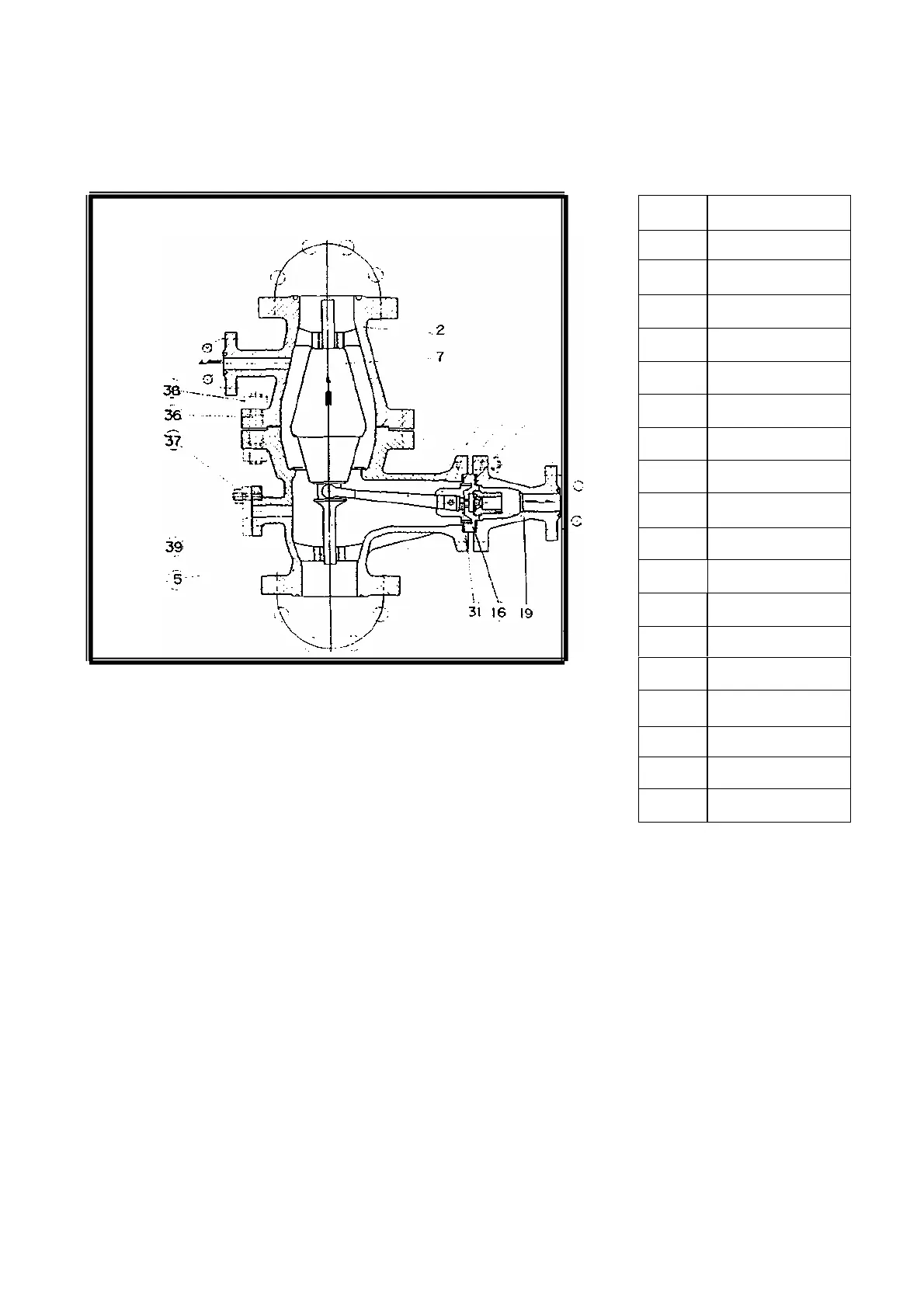
illustrated in fig. 14 and 14a,
No.
Name of Part
1 Body
2 Cover
3 By-Pass Outlet
5 Bearing
7 Cover
16 Seal
19 Venturi
23 Rocker Guide
24 Rocker
29 Arbor
30 Washer
31 Slide
36 Bolt
37 Stud Bolt
38 Nut
39 Blind Flange
40 Seat packing
41 Sest Packing
Each by-pass non-return valve is selected and supplied for the particular operating conditions pertaining to a given pump.
The lift of the by-pass non-return valve cone increases as the rate of flow approaches its maximum. The slide valve rod
connects the valve cone with the slide valve of the by - pass outlet. When the valve cone lifts, the slide valve slides, closing the
by - pass when a given minimum flow is exceeded, resp. opening it when the flow drops below the minimum.
The minimum rate of flow, at which the valve opens, is selected large enough to obviate undue overheating within the pump
(section 2.3.).
- 12 -