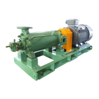
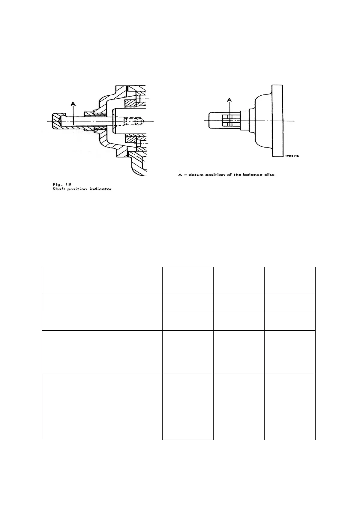
The shaft position indicator is situated on the bearing bracket at the discharge end of the pump (see fig. 18). When the
pump leaves our works, the measuring edge or marking A on the shaft stub is adjusted to the median position on the wear
indicator. The distance between adjacent markings is 1. 5 mm. When the measuring edge has moved axially towards the
suction end by an amount of 1. 5 mm approx., this indicates that wear is so severe that the balancing device must be inspected
and over-hauled. The worn components (6020, 6010) must be touched up or replaced by new ones. If necessary, and the
measuring edge A must be reset.
On the occasion when the balancing device components are touched up or renewed, the radial clearances at the seaIing
gaps between rotating and stationary parts should be checked. A rough and ready method of doing this consists in raising the
rotor and measuring the resulting clearance, preferably close to the final stage impeller. Too great a clearance will upset the
axial thrust balance, and give rise to rapid wear of the balancing device. If necessary, the worn components should be replaced
by new ones.
The table below lists the clearances which should not be exceeded :
*) If the wear rings and spacer sleeves are of chrome steel, the above listed clearances should be slightly increased . This is also true
where the materials of construction used have different heal elongation coefficients and, as a result, excessive closing-in of the clearances
could take place when fluids are pumped at high temperatures.
Clearance in millimeters ( on diameter )
In new
Condition ÷)
Permissible
wear
Max.
permissible
clearance
Between impeller (2300) and wear ring (5020) 0.3 mm 1.2 mm 1.5 mm
Between spacer sleeve (5210) and diffuser
(1710)
0.3 mm 0.7 mm 1,0 mm
Between spacer sleeve at suction end (5251)
and suction casing (1060) For suction lift
operation 01 atmospheric suction pressure For
positive suction head operation
0,3 mm
1,0 mm
1,7 mm
1,7 mm
2.0 mm
2.7 mm
Between the hub of the balance disc (6010) or
the spacer sleeve
:
.5252) in the discharge
casing, ; and the discharge casing (1070), or in
MML sizes 200-350, between the 'pacer sleeve
in the discharge-casing (5252) and the bush M
18) in the discharge casing (1070)
0.3 mm
0.2 mm
0.5 mm
- 17 -
- 17 -