REMOVE THE R8 SPINDLE
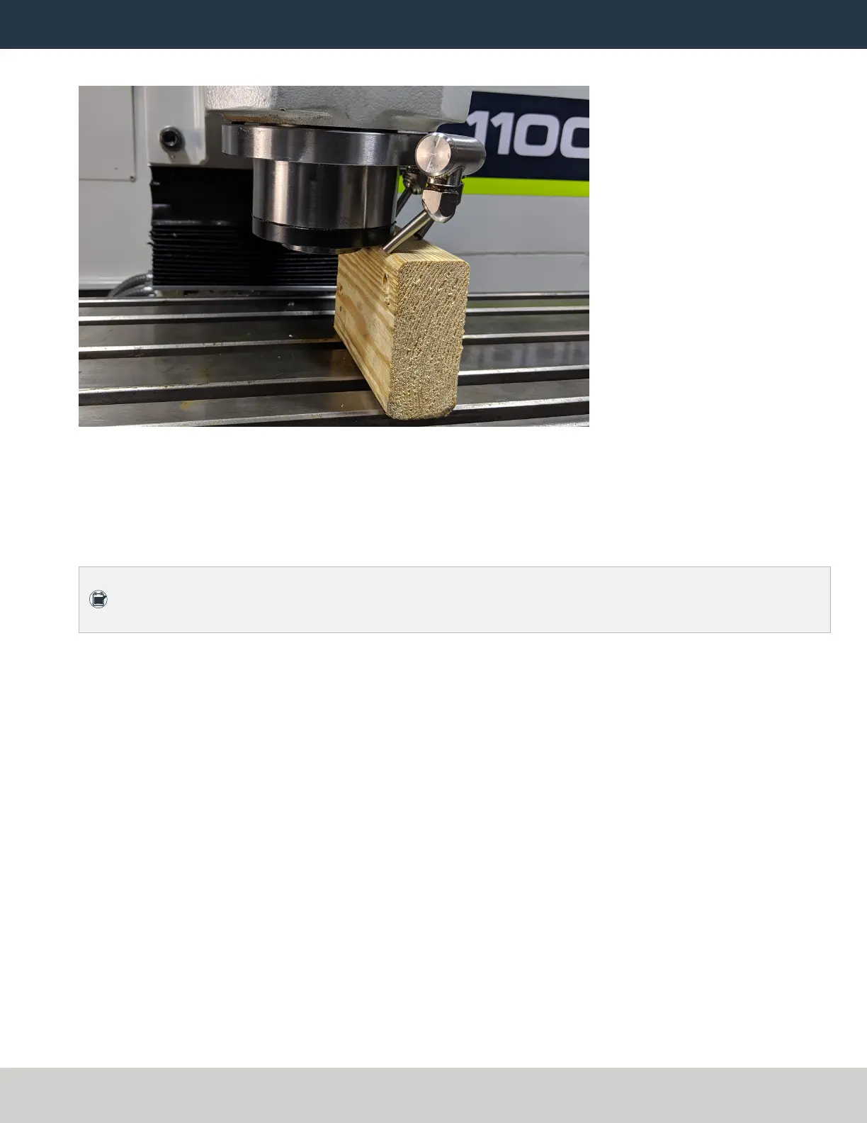
16. Put a 3 in. (7.6 cm) wooden block on the machine table below the spindle nose.
Figure 14: Spindle nose on the wooden block.
17. Slowly lower the spindle until the spindle nose is on the wooden block.
18. Remove the remaining socket head cap screw with a 6 mm hex wrench. Set it aside.
19. Slowly jog the Z-axis up (+Z) to raise the head casting until you have enough clearance to remove the spindle
pulley.
Note: You may need to move the spindle pulley back-and-forth as the Z-axis moves up in order to
remove it.
20. Continue to jog the Z-axis up (+Z) to raise the head casting until you can remove the spindle.
21. Discard the following items:
l Drawbar
l Power drawbar flange
l R8 collet
l Retention nut
l Spindle
l Spindle pulley
Page 16
©Tormach® 2021
Specifications subject to change without notice.
tormach.com
TD10705: Installation Guide: BT30 Spindle Upgrade Kit for 1100M+ (0521A)