REMOVE THE R8 SPINDLE
12. Power on the machine and the PathPilot controller.
a. Turn the Main Disconnect switch to ONon the side of the electrical cabinet.
b. Twist out the machine's red Emergency Stop button, which enables movement to the machine axes and
the spindle.
c. Press the Reset button.
d. Bring the machine out of reset and reference it.
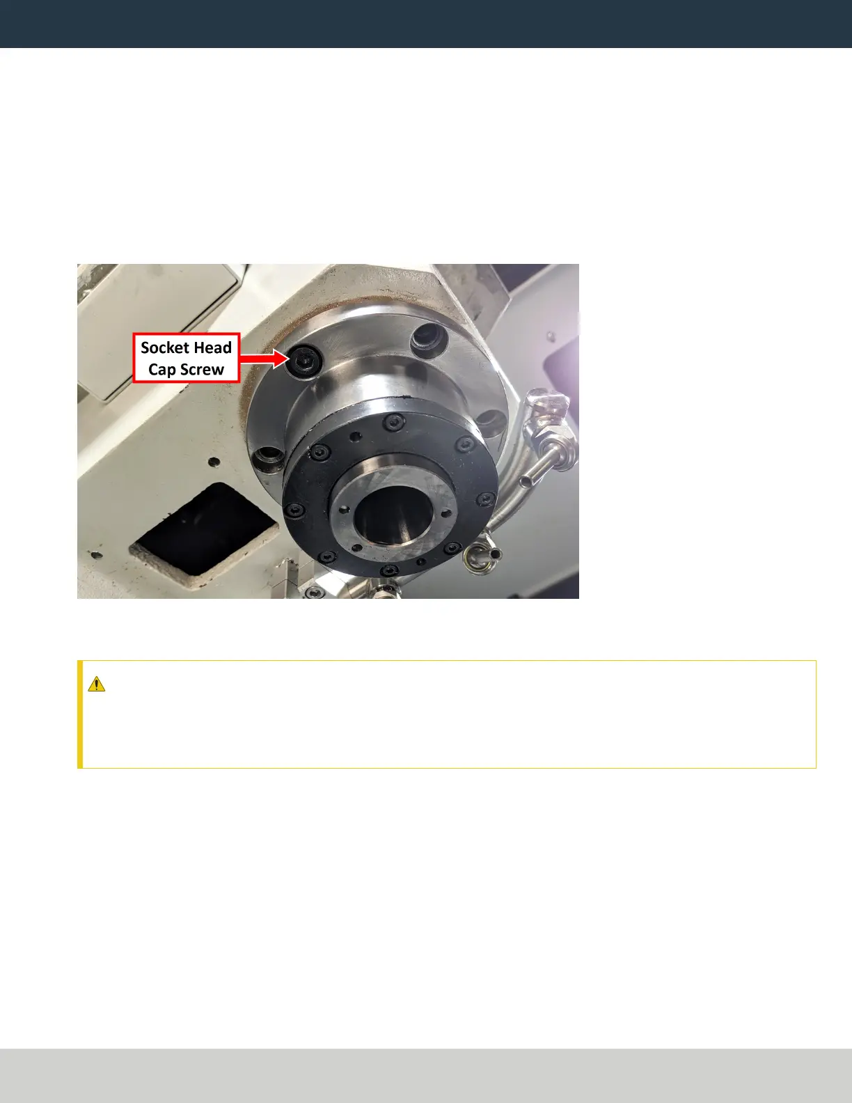
13. Remove five of the socket head cap screws that secure the spindle flange to the head casting with a 6 mm
hex wrench. Set them aside.
Figure 13: Six socket head cap screws retain the spindle flange.
14. Loosen the remaining socket head cap screw.
CAUTION! The spindle secures to the head casting with six socket head cap screws on the bottom face
of the spindle nose. Once you remove them, the spindle will begin to fall out of the casting. You must
rest the spindle on a block of wood before removing the final socket head cap screw. If you don't,
there's a risk of injury or machine damage.
15. Center the machine table: from the PathPilot interface, in the MDILine DROfield, type G20 G53 G1 X9
Y-5.5 Z0 F20. Then select the Enter key.
The machine table moves to the center position.
Page 15
©Tormach® 2021
Specifications subject to change without notice.
tormach.com
TD10705: Installation Guide: BT30 Spindle Upgrade Kit for 1100M+ (0521A)