INSTALL THE BT30 ENCODER
18. Find the encoder wire that you routed through the cord grip into the electrical cabinet. Then, connect each
encoder wire to the terminal block as detailed in the following table.
Connector Terminal Number Encoder Wire Color
J9.1 Red
J9.2 Green
J9.3 Brown
J9.4 White
J9.5 Gray
J9.6 Yellow
J9.7 Orange
J9.8 Black
J9.9 No Connection
19. Inside the electrical cabinet, remove the top wire trough cover and set it aside.
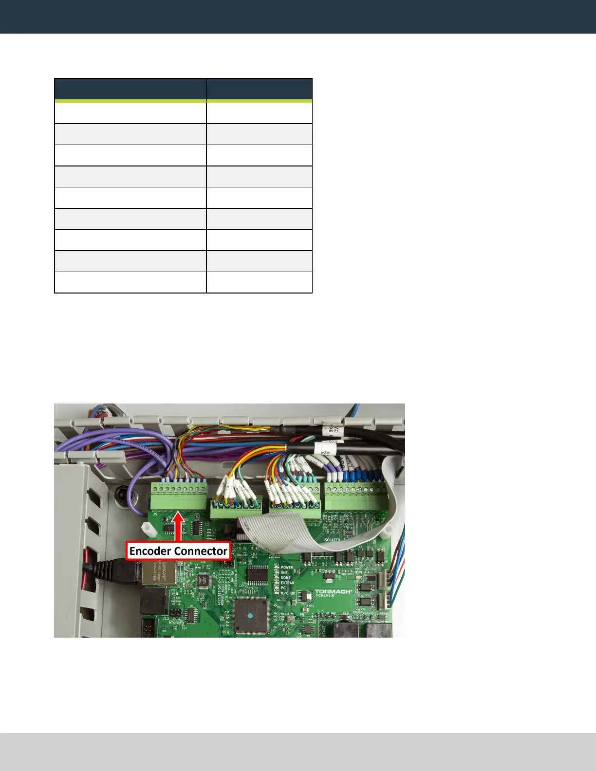
20. On the ECMv1.5 board, identify the J9 connector. For information, see "Machine Control Board (Sheet 5)"
(page34).
21. If necessary, remove any tabs from the wire troughs surrounding the connector so that you can easily make
wire connections.
22. Connect the terminal block with the encoder wires to J9 on the ECM v1.5 board.
Figure 20: Encoder wire connected to J9 on the ECM v1.5 board.
23. Organize the wires into the wire troughs.
24. Put back the top wire trough cover.
Page 21
©Tormach® 2021
Specifications subject to change without notice.
tormach.com
TD10705: Installation Guide: BT30 Spindle Upgrade Kit for 1100M+ (0521A)
 Loading...