INSTALL THE BT30 ENCODER
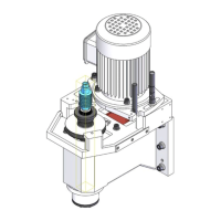
13. Identify the knockout holes on the top of the electrical cabinet. Remove one, and put one provided cord grip
in its place.
Figure 18: Cord grip installed in place of one knockout hole.
14. Find the encoder wire that you routed through the energy chain. Then, route the wire through the cord grip
and into the electrical cabinet.
15. Open the electrical cabinet door.
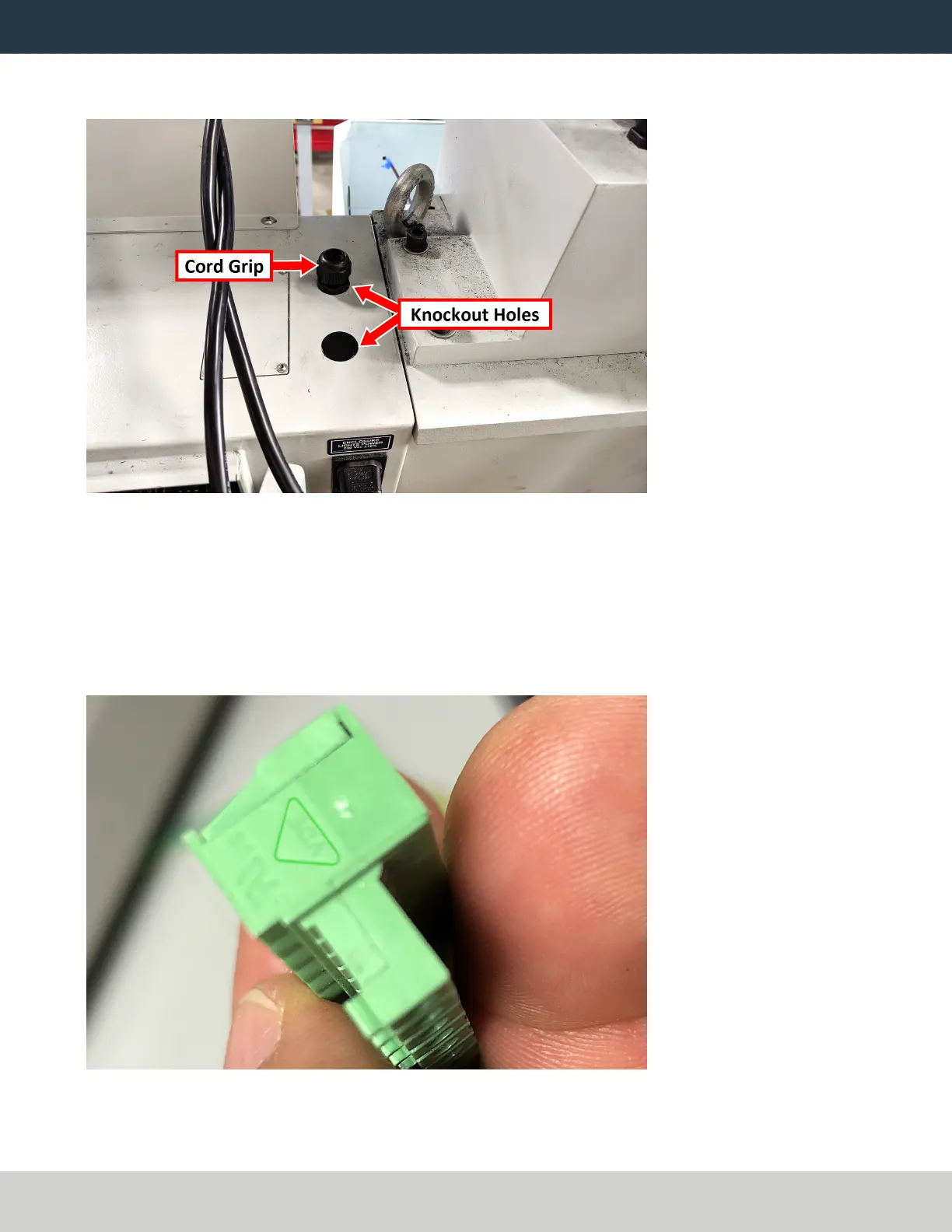
16. Find the 9-position terminal block provided in this kit.
17. Identify the pin connection locations on the terminal block. Pin 1 is closest to the small triangle on the
outside edge of the connector, as shown in the following image. Pins 2 through 8 follow in sequential order.
Figure 19: Triangle on the terminal block, which indicates the location of pin 1.
Page 20
©Tormach® 2021
Specifications subject to change without notice.
tormach.com
TD10705: Installation Guide: BT30 Spindle Upgrade Kit for 1100M+ (0521A)