INSTALL THE BT30 SPINDLE AND ALIGN THE ENCODER
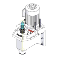
6. Identify the hole on the spindle flange as shown in the following image.
Figure 27: Hole on the spindle, which you must verify is pointing toward the machine column to install.
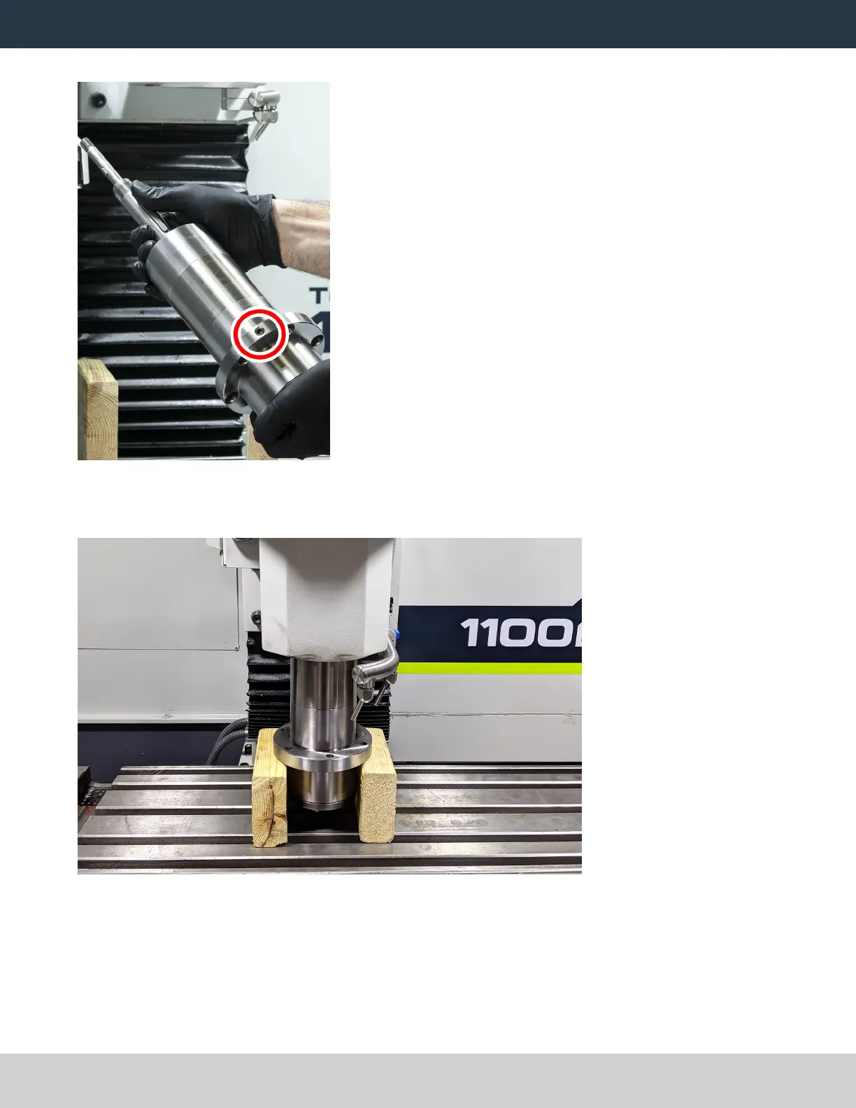
7. Turn the spindle so that the hole is pointing toward the machine column. Then, put the spindle between the
two blocks of wood on the machine table.
Figure 28: Z-axis jogged down to move the head casting over about half of the BT30 spindle.
8. Slowly jog the Z-axis down (-Z) until the head casting is flush with the spindle flange.
9. Find the six socket head cap screws that you set aside in "Remove the R8 Spindle" (page7). Secure the
spindle flange to the head casting with one of the socket head cap screws.
10. Slowly jog the Z-axis up (+Z) until you can remove the two blocks of wood from the machine table.
Page 27
©Tormach® 2021
Specifications subject to change without notice.
tormach.com
TD10705: Installation Guide: BT30 Spindle Upgrade Kit for 1100M+ (0521A)