INSTALL THE BT30 SPINDLE AND ALIGN THE ENCODER
11. Install the five remaining socket head cap screws into the spindle flange.
12. Working in a star pattern, tighten all six socket head cap screws to 20 ft lbs.
13. Install the encoder ring with the magnetic ring pointing up (away from the machine table). Then, remove
any stickers from the encoder ring.
14. Position the encoder tangent to the encoder ring, setting the distance using a piece of paper (approximately
0.003 in.).
15. Tighten the two flange screws to secure the encoder in place. Remove the shim.
16. Rotate the spindle by hand to confirm that there's no risk of entanglement.
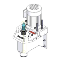
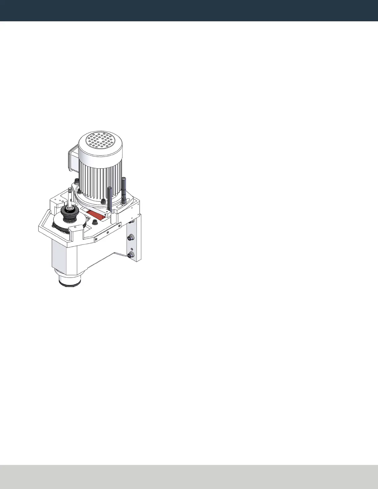
17. Install the pulley and power drawbar flange over the top of the spindle as shown in the following image.
Figure 29: Encoder ring, pulley, and power drawbar flange installed.
18. Reinstall the retention nut with the provided spanner wrench. Secure it by tightening its three set screws
with a 3 mm hex wrench.
Page 28
©Tormach® 2021
Specifications subject to change without notice.
tormach.com
TD10705: Installation Guide: BT30 Spindle Upgrade Kit for 1100M+ (0521A)