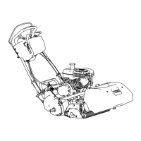
TheGearBoxAssembly
g323289
Figure2
1.Gearboxassembly4.Clevispin
2.Driveshield
5.Inputshaft
3.Cotterpin
Thegroomergearboxassemblyislocatedontherightsideofthecuttingunit.
RemovingtheGearBoxAssembly
RefertoFigure2forthisprocedure.
1.Removethecuttingunitfromthemachineandplaceitonalevelwork
surface.
2.Removethegroomerreelassembly;refertoRemovingtheGroomerReel
(page9–19).
3.Removethedriveshield.
4.Installa5/16–18X5/8inchsquareheadsetscrew(T orop/n1-803022)inthe
endofthedriveshaftandtightento13N·m(120in-lb);refertoFigure3.
5.Removethecotterpinandclevispinfromtheheightadjustmentrodatthe
frontofthegroomergearbox.Discardthecotterpin.
6.Tipupthecuttingunittoaccessthebottomofthereeltoremovethedrive
shaftassembly.
GreensmasterFlex1800/1820/2100/2120
Page9–9
UniversalGroomer(Optional):ServiceandRepairs
12188SLRevD

 Loading...