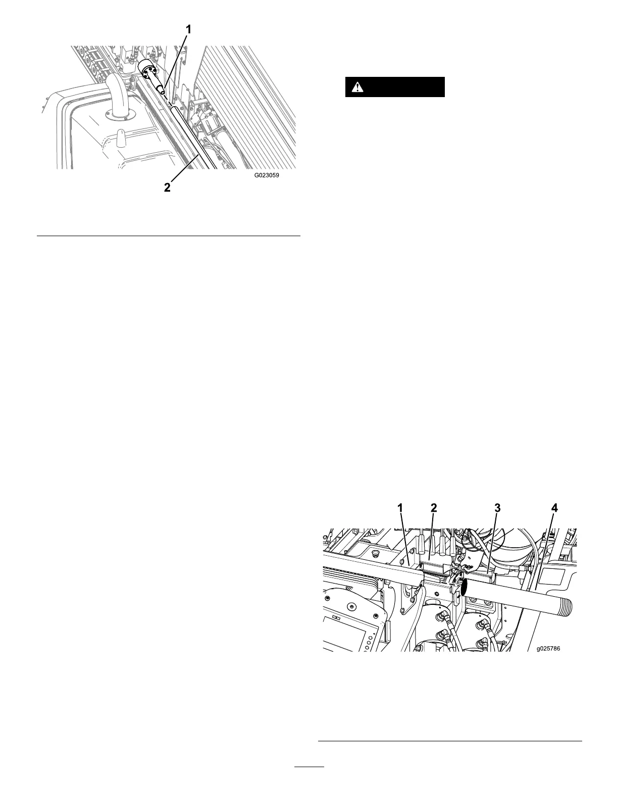
Figure50
1.Drillspindle2.Pipe
7.Continuetomovethedrillcarriageslowlydownthe
frameuntilthemalethreadsonthepipeareunder
thethread-joint-compoundapplicatorandapply
thread-jointcompoundtothethreads.
8.Releaseandretractthepipegripper,rotatingitallthe
wayouttothethirdrowofpipes.
Important:Ensurethatyoufullyretractthe
pipegripperandrotateitallthewayoutorthe
carriagemaycollidewiththegripper,damaging
themachine.
9.Continuetorotatethedrivespindleclockwise,until
themalepipethreadsarefullyseatedintothesonde
housingortheleadbar.
Note:Torquethethreadsto2305N-m(1700ft-lb).
InstallingtheDrillHead
1.Usingtheexit-side-lockouttransmitter,enabletheexit
sidelockout.
WARNING
Ifthedrillrotatesorextendswhileyouor
othersaremanuallyworkingonthedrillbitor
pipeinfrontofthemachine,theworkercould
getcaughtinthebitorpipecausingserious
injury,amputation,ordeath.
•Enabletheexit-sidelockoutonthe
exit-side-lockouttransmitterbefore
approachingthedillbitorpipewhen
attachedtothemachine.Thiswilldisable
thedrillcarriage.
•Donotwearlooseclothingorjewelrywhen
workingonadrillbitorpipeattachedto
themachine.Tielonghairupandoutof
theway.
2.Handthreadtheleadbarontothepipethreadsthen
clearawayfromthefrontofthemachine.
3.Whentheareaisclearofpeople,disabletheexit-side
lockoutusingtheexit-side-lockouttransmitter
(theOK-to-Drilllightonthecontrolpanelshould
illuminate);presstheexit-side-lockout,resetswitchon
thecontrolpanel.
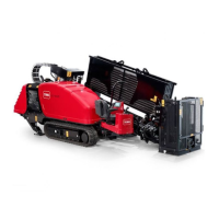
4.Pullthedrillpipeandleadbarbackthroughthepipe
guideandintothewrenches,aligningthethickened
upperjointoftheleadbarwiththeupperwrench
(Figure51).
Important:Donotclampthewrenchonthebody
ofapipeoritmaydamagethepipe.Gripthepipes
onthethickenedareanearthejoint.
Figure51
1.Drillpipe
3.Lowerwrench(stationary
wrench)
2.Upperwrench
(makeup/breakout
wrench)
4.Leadbar
50