Step
4
Installing the Control Rods
Parts needed for this step:
2
Control rods
2
Cotter pin
2
Clevis Pin
2
Washer
2
Hairpin cotter pin
Procedure
1. Install the control rods into the upper control
bar and the blade control bail. Secure the
control rods with 2 cotter pins ( Figure 9 ).
Figure 9
1. Control rod 3. Blade control bail
2. Upper control bar
4. Cotter pin
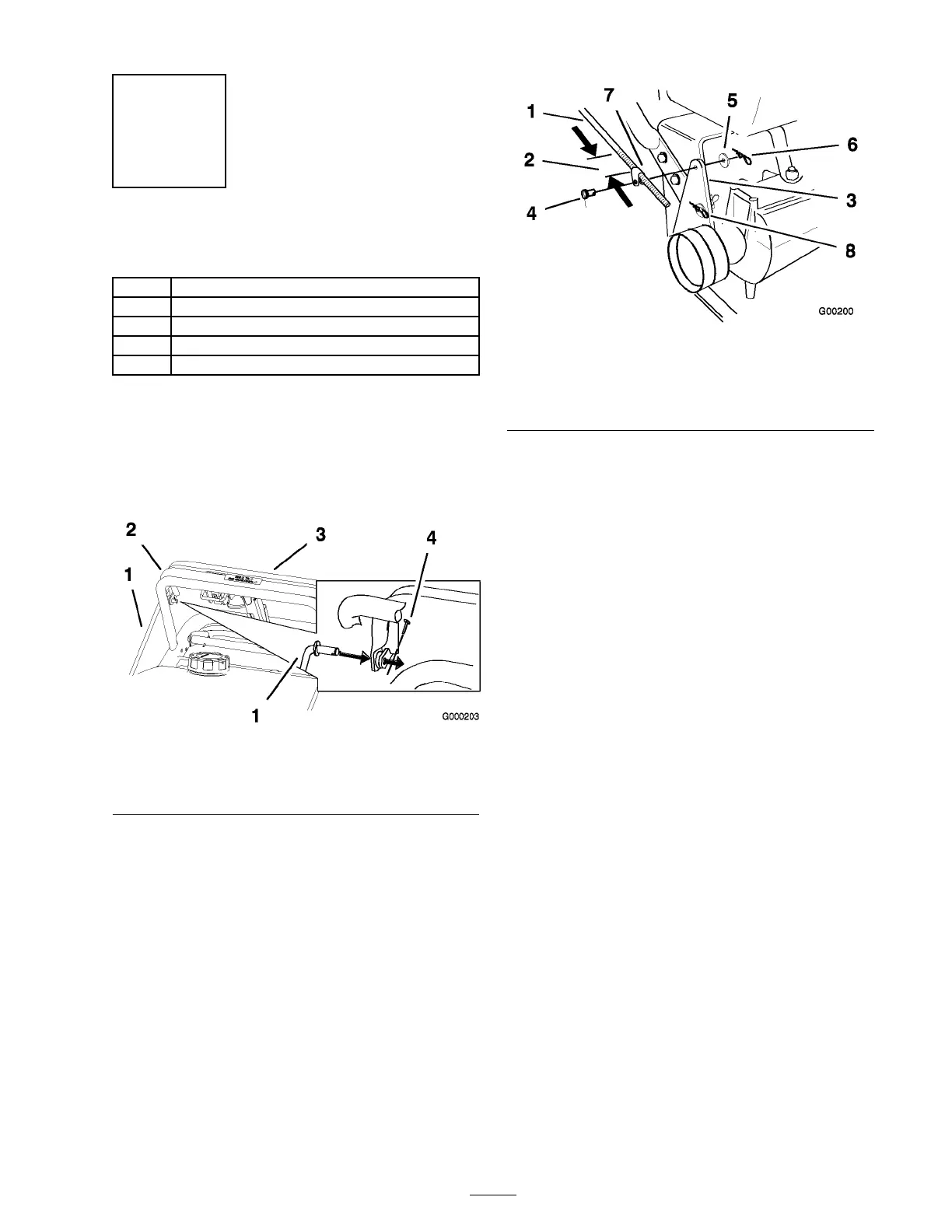
2. Mak e sure the rod fittings are equal distance
onto eac h control rod. T he rod fittings should
be appro ximately 3-1/2 inc h (89 mm) from
the star t of the threads for the handles lo w est
position ( Figure 10 ).
3. Slide clevis pins through rod fittings and
mounting holes in idler brac k ets (from outside)
( Figure 10 ). Secure with w ashers and hair pin
cotters ( Figure 10 ).
Note: Mak e sure brak e rod is installed in
front (F) mounting hole in idler brac k et.
Figure 10
1. Control rod and tting 5. Washer
2. 3-1/2 inch (89 mm)
6. Hairpin cotter pin
3. Idler bracket 7. Rod tting
4. Clevis pin 8. Hole F
4. Chec k the g ap betw een upper control bar and
fix ed bar with wheel dri v e fully eng ag ed. Gap
should be appro ximately 1 to 1-1/4 inc h (25-32
mm) ( Figure 11 ).
Note: T he upper control bar and fix ed bar
m ust be parallel when the upper control bar
is in the eng ag ed, dri v e , neutral, or brak e
positions .
5. Chec k the operation. If adjustment is required,
remo v e hair pin cotter , w asher and clevis pin
securing control rod fitting to idler brac k et.
6. T hread fitting up or do wn on rod until proper
position is attained and install the fitting into
the idler brac k et with clevis pin, w asher and
hair pin cotter .
15