Figure 22
1. Mower
2. Lift handle
3. Add or remo v e spacers if needed and then
align holes and inser t hair pin cotter ( Figure 23 ).
Note: Spare height-of-cut spacers ma y be
stored on posts and retained b y a hair pin cotter .
Important: All f our hair pin cotter pins
must be in the same hole location and with
the cor r ect n umber of spacer s f or a lev el
cut.
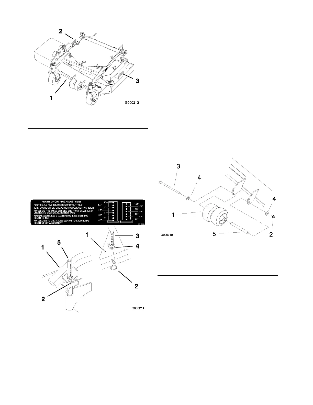
Figure 23
1. Carrier Frame
4. Spacers
2. Hairpin Cotter
5. Back height-of-cut post
3. Front height-of-cut post
Adjusting the Center Gage
Wheels
T he g ag e wheels need to be adjusted in the proper
hole location for eac h height-of-cut position.
T here needs to be 3/8 inc h (10 mm) minim um
clearance abo v e the g round.
1. After adjusting height-of-cut, c hec k the g ag e
wheels so that there is a minim um of 3/8
inc h (10 mm) clearance abo v e the g round
( Figure 24 ).
2. If adjustment is needed, remo v e the bolt,
w ashers and n ut ( Figure 24 ).
3. Select a hole position so the g ag e wheels are a
minim um of 3/8 inc h (10 mm) off the g round
( Figure 24 ).
4. Install the bolt, w ashers and n ut ( Figure 24 ).
Figure 24
1. Center Gage Wheels and
Spacer
4. Washer
2. Nut 5. Spacer
3. Bolt
Adjusting the Handle Height
T he handle position can be adjusted to matc h the
operator’ s height preference .
1. R emo v e hair pin cotter , w asher and clevis pin
securing control rod fitting to idler brac k et
( Figure 25 ).
26