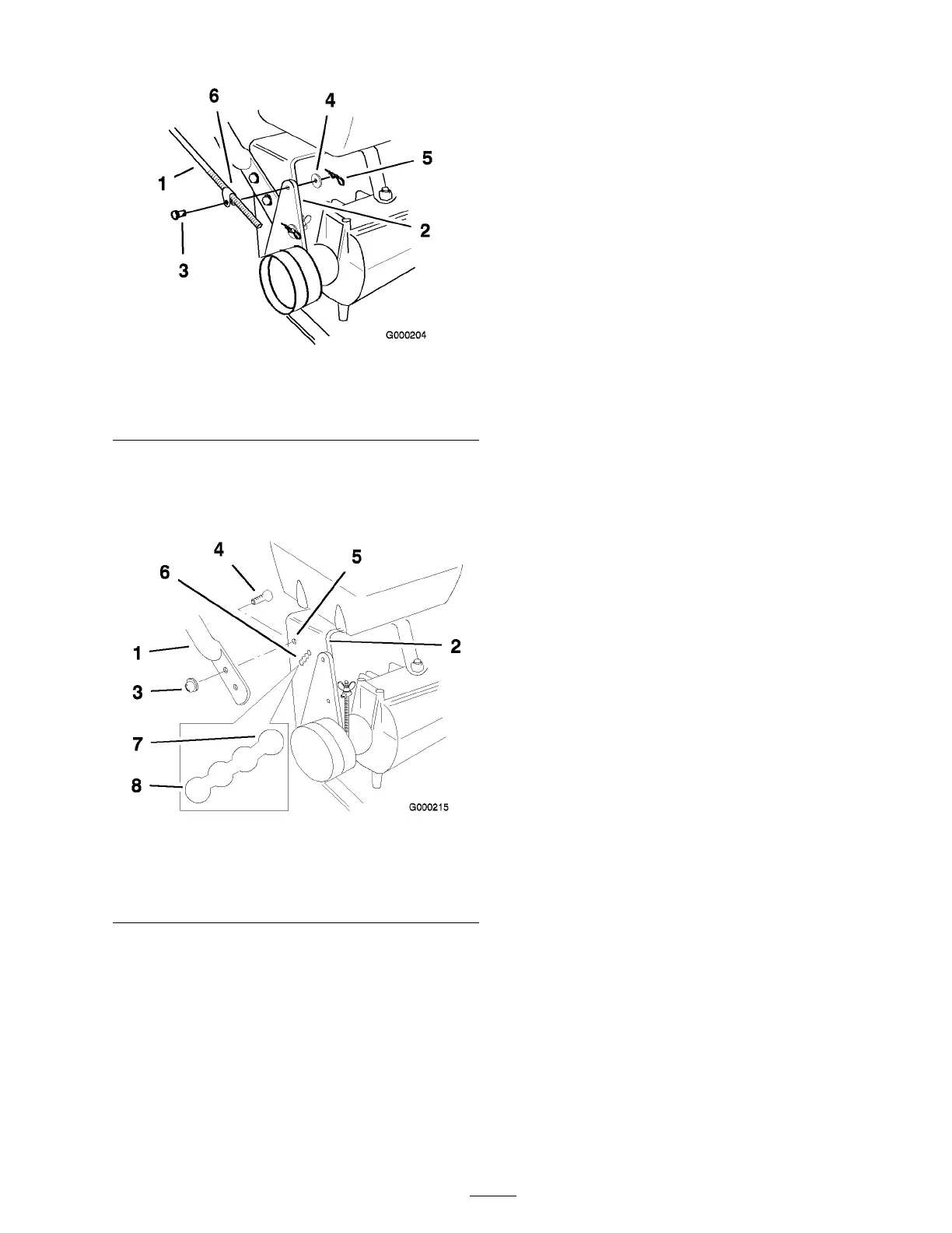
Figure 25
1. Control rod and tting 4. Washer
2. Idler bracket
5. Hairpin cotter pin
3. Clevis pin 6. Rod tting
2. Loosen the upper flang e bolts (3/8 x 1 inc h)
and flang e n ut securing handle to rear frame
( Figure 26 ).
Figure 26
1. Upper handle 5. Upper mounting hole
2. Rear frame 6. Lower mounting holes
3. Flange nut, 3/8 inch
7. Low position
4. Flange bolt, 3/8 x 1 inch 8. High position
3. R emo v e the lo w er flang e bolts (3/8 x 1 inc h)
and flang e n uts securing handle to rear frame
( Figure 26 ).
4. Pi v ot handle to desired operating position and
install lo w er flang e bolts (3/8 x 1 inc h) and
flang e n uts into mounting holes . Tighten all
flang e bolts .
5. T hread rod fitting up or do wn on rod until
proper position is attained and install into
fitting to idler brac k et with clevis pin, w asher
and hair pin cotter . R efer to Installing the
Control R ods in Setup , pag e 12 .
6. Chec k the parking brak e adjustment. R efer to
Chec king the Brak es in Brak e Maintenance ,
pag e 37 .
27