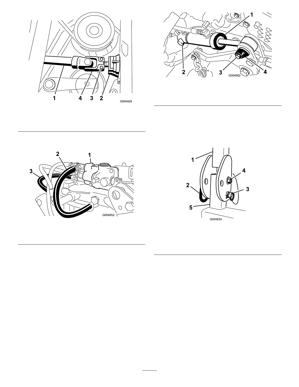
Figure11
1.Driveshaft
3.Bolt
2.Gearbox
4.Rollpin
8.Routeandconnectthehydraulicpressureandtank
hosestothevalve(Figure12).
Figure12
1.Controlvalve
3.Pressurehose
2.Tankhose
9.Installtherearofthedeckliftcylinderontothepivot
pinandsecurewiththeretainingring(Figure13).
10.Securethefrontoftheliftcylindertothemowerframe
withthecylinderpinandscrew(Figure13).
Figure13
1.Deckliftcylinder3.Screw
2.Retainingring
4.Cylinderpin&screw
11.PositiontheROPSassemblyontotheROPSposts.
Installthebolt,nut,hairpincotterandpinsecuring
eachROPSassemblytotheROPSposts(Figure14).
Note:Ifinstallinganalliedsuppliersmowerdeck,
ROPSKit,partno.117–9179mustbeinstalled.
Figure14
1.ROPS4.Bolt&nut
2.Pin
5.ROPSpost
3.Cotterpin
12.Startthemachine,raiseandlowerthedeck.Checkfor
leaksandmakesurethehosesdonotrubagainstthe
frame.
InstallingthePolarTracKit
1.Removethetractionunitfromtheshippingpallet.
2.Placeajackstandundereachwheelmotorandaoor
jackundertherearbumper(Figure15)orsuspend
fromaoverheadhoist.
13