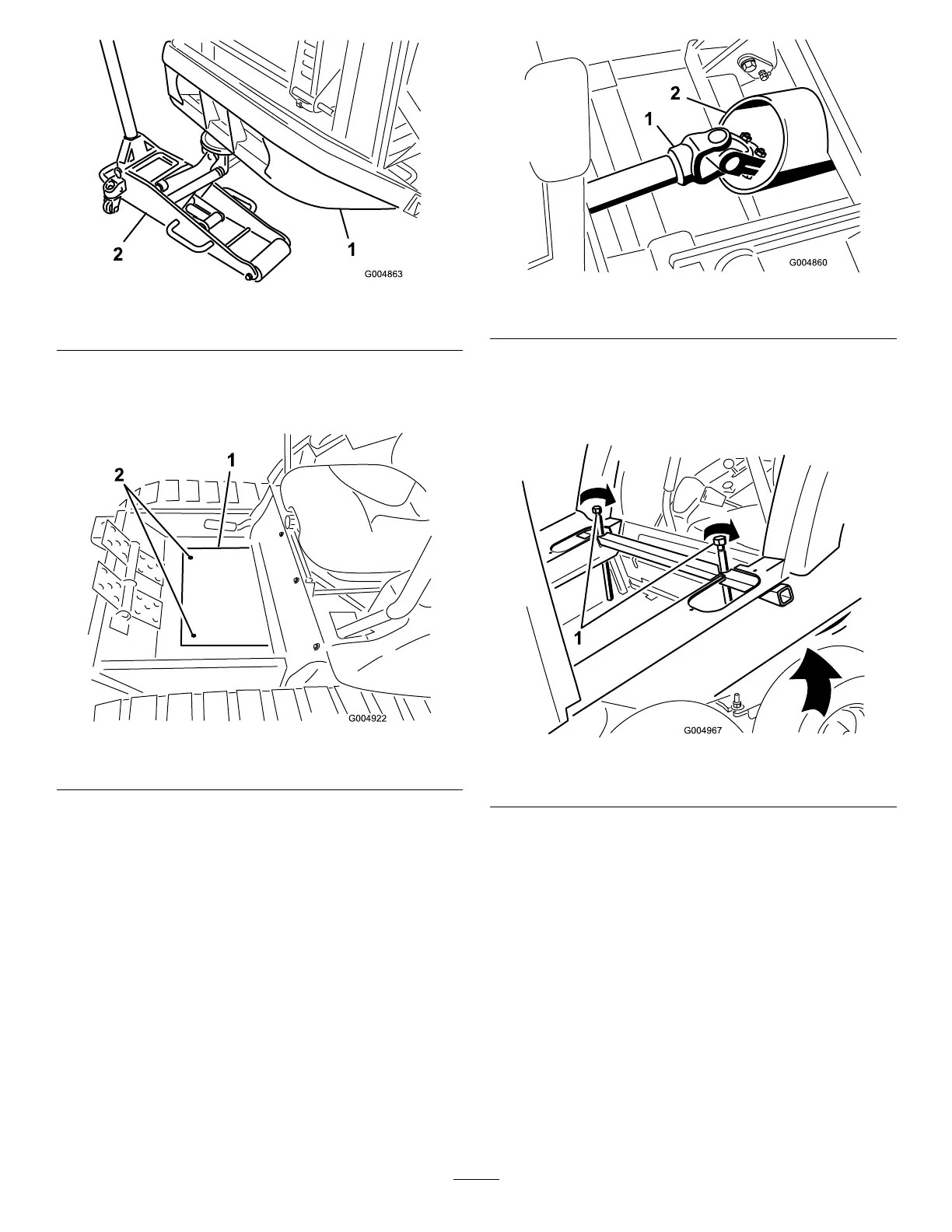
Figure15
1.Rearbumper2.Floorjack
3.Removethetwoscrewssecuringthewinterframeoor
platecovertotheoorandremovetheplate(Figure
16).
Figure16
1.Floorplatecover2.Mountingscrews
4.Carefullyrollthewinterframeassemblyintoposition
whileroutingthedriveshaftthroughtheframetube
(Figure17).
Figure17
1.Driveshaft
2.Frametube
Note:Iftherearofthecabisnothighenoughtoclear
thecontrolhandles,evenlytightenthejackingbolts
oneachsideofthecabjacktubetoraisetherearof
thecab(Figure18).
Figure18
1.Jackingbolts
5.Routethehosesasfollows:
•Routethetankhoseundertheliftcylinderand
betweenthecylindermountingbracketstothe
valve(Figure19).
•RoutethepressurehosealongsidethePTOshaft
tothevalve(
Figure19).
Note:Toemphasisthehoserouting,thehosesare
shownwithoutthehosecoversinstalled.
14