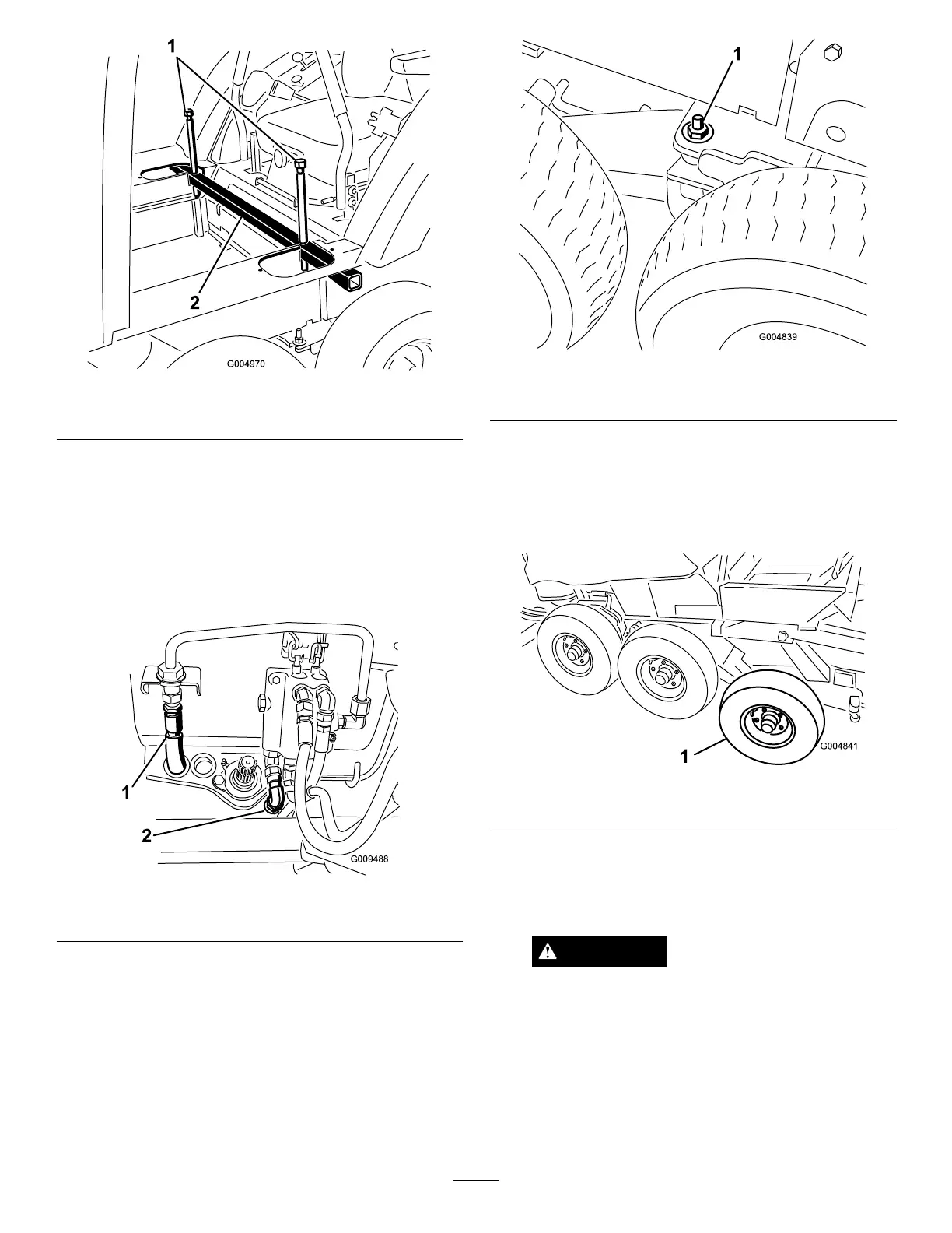
Figure27
1.Jackingbolts
2.Cabjacktube
14.Connectthehydraulicpressurehosetothevalvehard
lineandthetankhosetothevalve(Figure28).Retain
thehoseplugsforthesummerchangeover.
Note:Makesurethehosesarenotekinkedorare
rubbingagainstanymovingparts.
Note:Adjusttheangleofthettingstoaccommodate
theroutingofthehoses.
Figure28
1.Pressurehose2.Tankhose
15.Raisetherearofthemachineuntil2jackstandscanbe
positionedunderthereartubeataheightthatsupports
thereartires2.5to7.5cm(1to3inches)offofthe
ground.
16.Lowertheoorjacksotherearframerestsonthejack
stands.Positiontheoorjackunderthecenterofthe
frontliftarmpivottube.
17.Removetheatwasher(1/2inch)andnut(1/2inch)
installedonthestudonthebogiepivot(
Figure29).
Figure29
1.Washer&nutonthebogiepivotstud
18.Raisetheoorjackuntilthefronttiresareoffofthe
groundhighenoughtoinstallthetrackbeneaththem
andsupporttheframewithjackstands.
19.Removethefrontandcentertiresfromthewinter
assembly(Figure30).
Figure30
1.Fronttire
20.Carefullyliftthetracksovertherearwheelandfront
hubs.Thedirectionofthetrackrotationisprintedon
thetrack.TheVdesignintherubbertrackmustpoint
forward.
CAUTION
Thetrackguideshavemanypinchpoints.
Carefullygrasptherubbertrackontheouter
edgesoutboardofthesteelguideswhen
movingthetrack.
21.Adjusttheoorjacktoasuitableheighttoinstallthe
fronttire.Withahelper,liftthefrontofthetrack
enoughtocarefullyinstallthefronttires(
Figure31).
17
 Loading...

