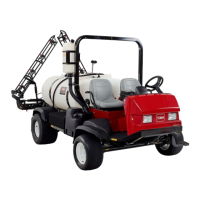
Figure9
1.Flowmeterassembly4.Hose,longer
2.Hose,shorter5.Flowmetermounting
bracket
3.Manifold,boomvalve
8.Installthehosetotheowmeter.Lightlylubricate
thebarbontheowmeterwithanon-petroleum
basedlubricant,suchasvegetableoil.Theow
directionarrowshouldbepointingawayfromthe
installedhose.Thiswaytheowdirectionarrowwill
bepointingtotherightsideofthemachineonce
installed.
Important:Installingtheowmeterwiththe
arrowpointedinthewrongdirectioncanresult
indamagetotheowmeter.
9.Slidethehoseclampintopositionovertheowmeter
barbandtightentosecure.
10.Locatetheremaininghoseinlooseparts.Lightly
lubricatetheexistingbarbontherightsideofthe
boomvalvemanifoldwithanon-petroleumbased
lubricant,suchasvegetableoil.Installthehose
ontotheboomvalveinletbarbttingcompletely
(
Figure9).
11.Slidetwohoseclampsontothehoseandrouteopen
endofthehosearoundtherightuprightofthe
boommountingframeuptotheinstalledowmeter
bracket.
Important:Hosesmayneedtobetrimmedto
avoidkinks.
12.Lightlylubricatetheopenbarbontheowmeterwith
anon-petroleumbasedlubricant,suchasvegetable
oil.Installtheopenendoftheroutedshorterhose
ontotheoutletbarbttingoftheowmeter.
13.Securetheshorterhosetothemanifoldand
owmeterrespectivelybyslidingthehoseclamps
intopositionsoverthebarbandtightening.
14.Securetheowmeterassemblytotheowmeter
bracketwithhoseclamps.
15.Locatethespraysystemwiringharnessroutedto
theboomvalvemanifold.Locatethecappedround
connectorlabeledowmeter.
16.Removethecaptoexposethethree-pinplugand
connectittothewirecomingfromtheowmeter.
Securethelockingringsanylockingringsifavailable.
Inspectallworktoensureallhoseclampsaretightened.
RemovingtheBoomBypassAssembly
Thissystemisdesignedtoworkwithadiaphragmpump
andoperateswithouttheboombypassassembly.
Important:Beforeoperatingthespraysystemwith
theconsolecomputer,theboombypassmanifold
mustberemoved.
1.Removethenutsecuringthebypasshosetting
totheboommanifold.Underthemaintank,
disconnecttheotherendofthehoseassemblyfrom
themaintank.Retainallfasteners.
Note:Retainallpartsfromthishoseassemblyso
theElectricHoseReelKitorSprayGunKitcanbe
properlyinstalledatalatertime.
2.Removeallthreeforksholdingthebypassmanifold
ontotheboomvalves(
Figure10).Retainall
fasteners.Removethebypassmanifold.
Figure10
1.Boomvalves
3.Manifold,boombypass
2.Forksholdingbypass
manifold,remove
4.Bypassmanifoldassembly
forks,donotremove
8