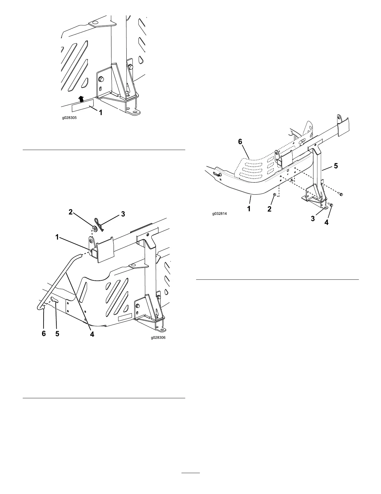
g028305
Figure 13
1. Draw bar decal
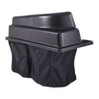
5. Install the bent, ared end of a rod into the keyed
slot in the left side of the machine frame, and
move the rod rearward to seat it in the frame
( Figure 14 ).
Note: Repeat this step for the right side of the
machine.
g028306
Figure 14
Left side shown
1. Pivot frame hole 4. Support rod
2. W asher 5. Keyed slot, existing
3. Hairpin cotter
6. Bent, ared end of rod
6. Insert the bent ends of the rods into the
attachment mount as shown in Figure 14 and
secure the end of each rod with a washer and
hairpin cotter .
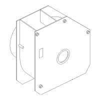
For 201 1 through 2014 Models
Only
Note: The stabilizer bracket is not used on 201 1
through 2014 models.
Note: For 201 1 through 2014 models, the rear-engine
guard is optional for this bagger .
1. Install the pivot frame to the machine frame as
shown in Figure 15 . Secure the pivot frame to
the machine frame using 2 bolts (5/16 x 1 inch)
and 2 locknuts (5/16 inch).
g032814
Figure 15
1. Machine frame 4. Bolt (5/16 x 1 inch)
2. Locknut (5/16 inch) 5. Pivot frame
3. Hole 6. Rear-engine guard
(optional)
2. Secure the pivot frame to the bottom of the
machine frame using 2 self-tapping screws (5/16
x 3/4 inch) as shown in Figure 16 .
1 1