RemovingandInstalling
theMowerBlade(s)
Replacethebladeifithitsasolidobject,isoutof
balance,orifitisbent.AlwaysusegenuineT oro
replacementbladestoensuresafetyandoptimum
performance.
1.Raisethemowerdecktothehighestposition,
engagetheparkingbrake,shutofftheengine,
andremovethekey.
Note:Blockthemowerdecktopreventitfrom
accidentallyfalling.
2.Grasptheendofthebladeusingaragorthickly
paddedglove.
3.Removethebladebolt,anti-scalpcup,and
bladefromthespindleshaft(Figure129).
g004741
Figure129
1.Bladebolt2.Anti-scalpcup
4.Installtheblade,anti-scalpcup,andbladebolt
andtightenthebladeboltto115to149N∙m(85
to110ft-lb).
Important:Thecurvedpartoftheblade
mustbepointingtowardtheinsideofthe
mowerdecktoensurepropercutting.
Note:Afterstrikingaforeignobject,torqueall
ofthespindle-pulleynutsto115to149N∙m(85
to110ft-lb).
InspectingandSharpening
theMowerBlade(s)
Bothcuttingedgesandthesail,whichistheturned-up
portionoppositeofthecuttingedge,contributeto
agoodqualityofcut.Thesailisliftsthegrassup
straight,therebyproducinganevencut.However,the
sailgraduallywearsdownduringoperationdegrading
thequalityofcut,althoughthecuttingedgesare
sharp.Thecuttingedgeoftheblademustbesharp
sothatthegrassiscutratherthantorn,whichleaves
thetipsofthegrasslookingbrownandshredded.
Sharpenthecuttingedgestocorrectthiscondition.
1.Positionthemachineonalevelsurface,raise
themowerdeck,engagetheparkingbrake,put
thetractionpedalinNEUTRAL,putthePTOlever
intheOFFposition,shutofftheengine,and
removethekeyfromtheignition.
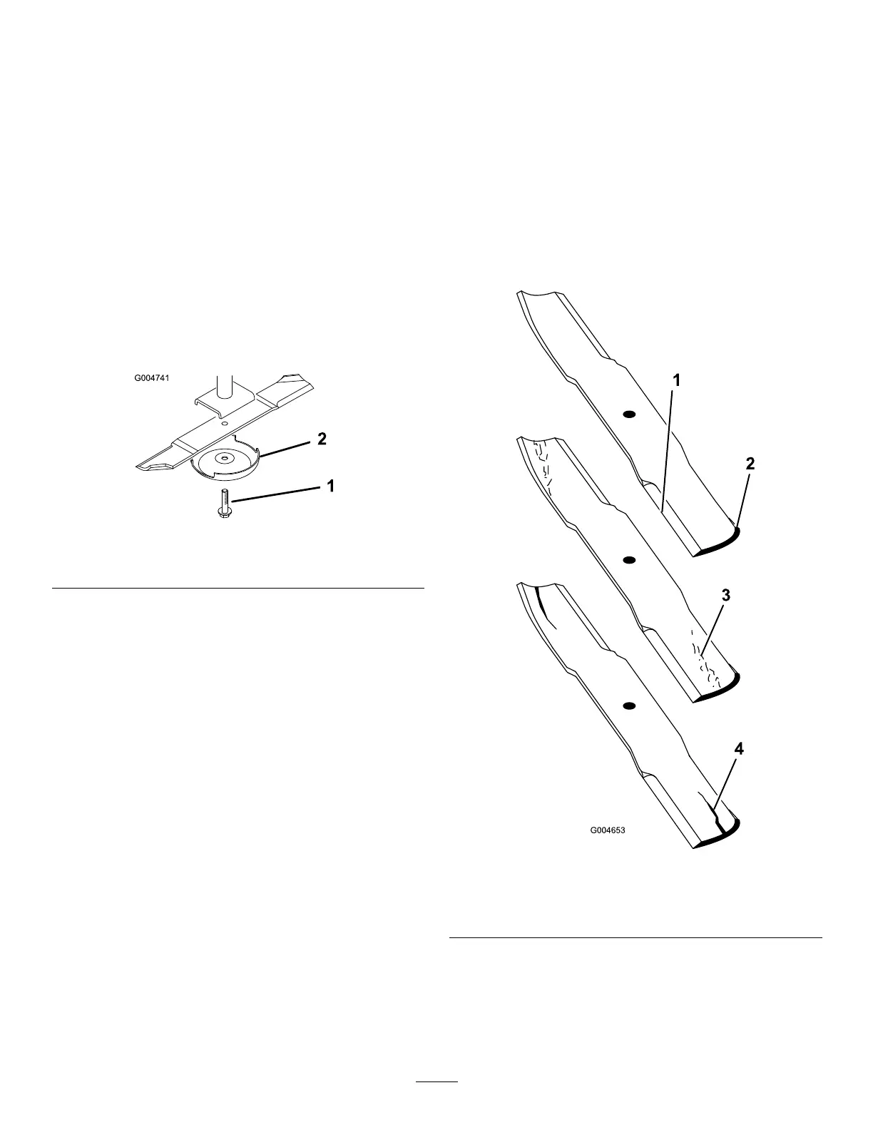
2.Examinethecuttingendsofthebladecarefully,
especiallywheretheatandcurvedpartsofthe
blademeet(Figure130).
Note:Becausesandandabrasivematerial
canwearawaythemetalthatconnectstheat
andcurvedpartsoftheblade,checktheblade
beforeusingthemower.Ifyounoticewear
(Figure130),replacetheblade.
g004653
Figure130
1.Cuttingedge3.Wear/slotforming
2.Curvedarea4.Crack
3.Examinethecuttingedgesofalloftheblades
andsharpenthecuttingedgesiftheyaredull
ornicked(Figure131).
Note:Sharpenonlythetopofthecutting
edgeandmaintaintheoriginalcuttingangle
84