g029758
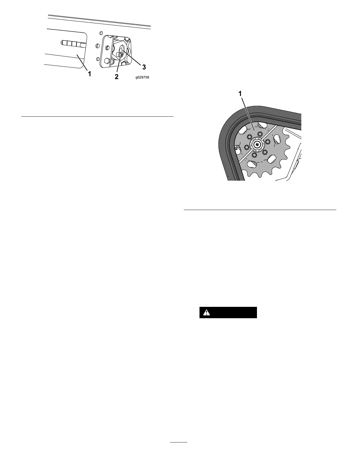
Figure59
1.Tensiontube3.Tensioningscrew
2.Lockingbolt
4.Usinga1/2inchdriveratchet,turnthetensioning
screwuntilthetensionblockalignswiththe
greenguideonthedecaloris1.3cm(1/2inch)
awayfromtherearofthetensiontubeslot
(Figure58).
Note:Turningthescrewcounter-clockwise
tightensthetrack;turningthescrewclockwise
loosensthetrack.
5.Aligntheclosestnotchinthetensionscrewto
thelocking-boltholeandsecurethescrewwith
thelockingboltandnut(Figure59).
6.Repeattheprocedurefortheothertrack.
7.Drivethemachine,thenparkthemachineona
levelsurface,engagetheparkingbrake,shutoff
theengine,andremovethekey.
8.Verifythatthetensionblockalignswiththe
greenguideofthedecaloris1.3cm(1/2inch)
awayfromtherearofthetensiontubeforboth
tracks(Figure58).Adjustifnecessary.
ReplacingtheTracks
MachineswithNarrow-WidthTracks
Replacethetrackswhentheyarebadlyworn.
1.Removeanyattachments.
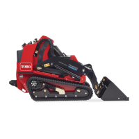
2.Parkthemachineonalevelsurface,ensuring
thatonly1sprockethalfisengagedwiththe
track(Figure60).
g259714
Figure60
1.Sprockethalf
3.Engagetheparkingbrake.
4.Lowertheloaderarmssothattheyare
approximately20to25cm(8to10inches)
abovetheframe.
5.Shutofftheengineandremovethekey.
6.Raisethemachineoffthegrounduntilyou
canaccesstheinsideofthetrackbeneath
themachine.Supportthemachineusingjack
stands.
Note:Usejackstandsratedforyourmachine.
WARNING
Mechanicalorhydraulicjacksmayfailto
supportthemachineandcauseserious
injury.
Usejackstandswhensupportingthe
machine.
7.Removethelockingbolt,spacer,andnut(Figure
57).
8.Usinga1/2-inchdriveratchet,releasethe
drivetensionbyturningthetensioningscrew
clockwise(Figure57andFigure61).
40