EasyManuals Logo

Toshiba B-SA4T Option Installation Manual

Toshiba B-SA4T
58 pages
To Next Page IconTo Next Page
To Previous Page IconTo Previous Page
Page #35 background imageLoading...
Page #35 background image
INSTALLATION PROCEDURE FOR OPTIONAL EQUIPMENT EO15-33001A
(Revision Date: Jan. 19, 2006)
6. Real Time Clock: B-SA704-RTC-QM-R
6- 4
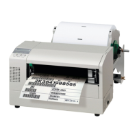
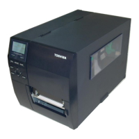
5. Pass the Interface Cable through the Cable Clamp, and between CN1 and CN2 on the MAIN PC
Board, as shown in the pictures below. For the B-SA4TP model, wind the cable on the two Cable
Clamps.
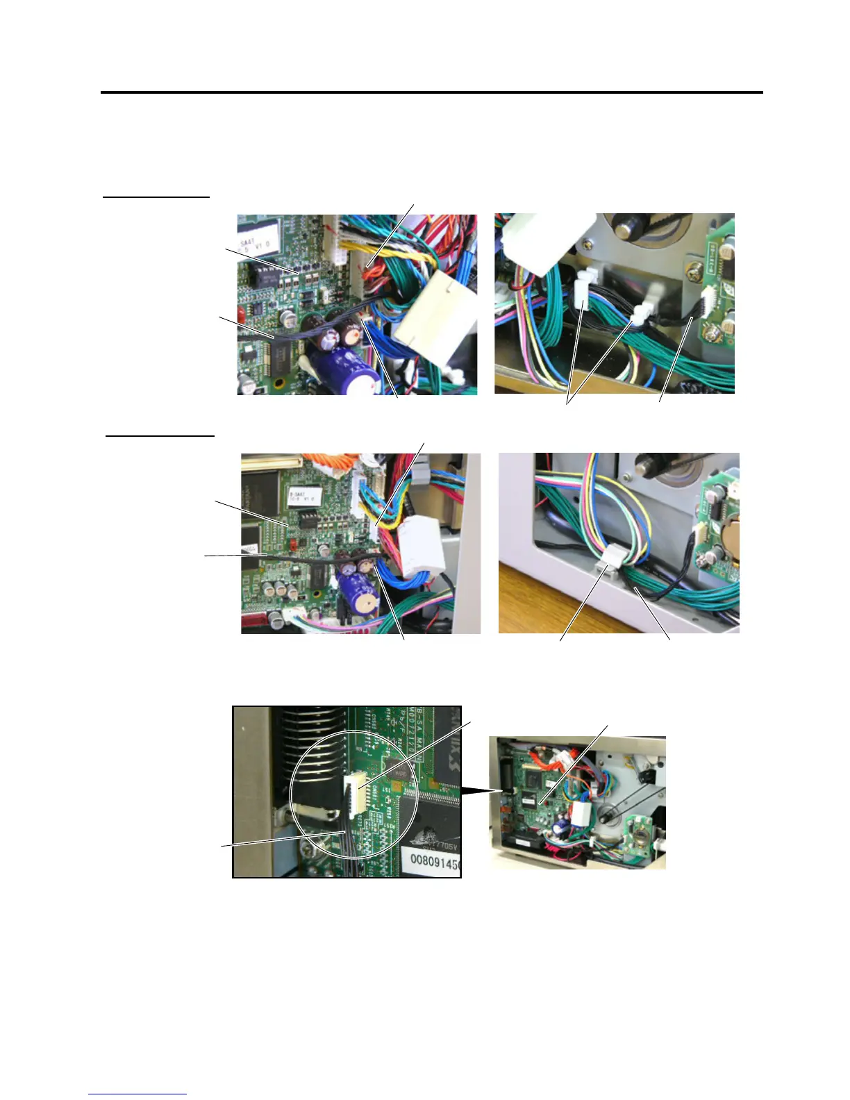
6. Connect the Interface Cable to CN501 on the MAIN PC Board.
7. Attach the Side Panel, removed in Step 2, back to the printer. Care must be taken not to catch the
Interface Cable by the Side Panel.
NOTE: When the B-SA704-IO-QM-R Expansion I/O Board or B-SA704-RS-QM-R Serial Interface Board was
removed beforehand, re-install it.
Cable Clamp
B-SA4TP Model
Interface Cable
Interface Cable
Connector CN2
Connector CN1
MAIN PC Board
B-SA4TM Model
Cable Clamp
Interface Cable
Interface Cable
Connector CN2
Connector CN1
MAIN PC Board
CN501
Interface Cable
MAIN PC Board

Other manuals for Toshiba B-SA4T

Questions and Answers:

Question and Answer IconNeed help?

Do you have a question about the Toshiba B-SA4T and is the answer not in the manual?

Toshiba B-SA4T Specifications

General IconGeneral
Print MethodThermal transfer and direct thermal
Resolution203 dpi
Print Width104 mm
InterfacesSerial, Parallel, USB
Optional InterfacesEthernet, Wireless
BarcodesCode 39, Code 128
2D CodesPDF417, Data Matrix, QR Code, MaxiCode
Operating Temperature5°C to 40°C (41°F to 104°F)
Storage Temperature-20 - 60 °C (-4 - 140 °F)
Humidity20% to 85% (non-condensing)
InterfaceUSB, Serial (RS-232), Parallel, Ethernet, Wireless

Related product manuals