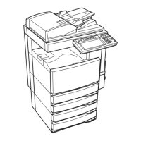
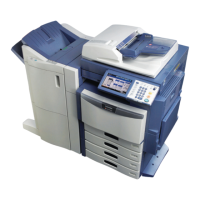
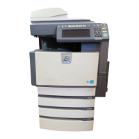
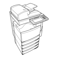
e-STUDIO350/352/353/450/452/453 © 2003 - 2008 TOSHIBA TEC CORPORATION All rights reserved
CONTENTS
2
3.5.3 Setting range correction ......................................................................................... 3-28
3.5.4 Setting range correction (Adjustment of background peak) ................................... 3-28
3.6 Adjustment of High-Voltage Transformer .......................................................................... 3-29
3.6.1 Adjustment ............................................................................................................. 3-29
3.6.2 Precautions ............................................................................................................ 3-38
3.7 Adjustment of the Scanner Section ................................................................................... 3-40
3.7.1 Carriages................................................................................................................ 3-40
3.7.2 Lens unit................................................................................................................. 3-45
3.8 Adjustment of the Paper Feeding System ......................................................................... 3-48
3.8.1 Sheet sideways deviation caused by paper feeding .............................................. 3-48
3.9 Adjustment of Developer Unit ............................................................................................ 3-49
3.9.1 Doctor-to-sleeve gap .............................................................................................. 3-49
3.10 Adjustment of the RADF (MR-3015).................................................................................. 3-52
3.10.1 Adjustment of RADF position ................................................................................. 3-52
3.10.2 Adjustment of RADF height.................................................................................... 3-57
3.10.3 Adjustment of skew ................................................................................................ 3-59
3.10.4 Automatic adjustment of sensors and initialization of EEPROM ............................ 3-60
3.10.5 Adjustment of aligning ............................................................................................ 3-61
3.10.6 Adjustment of aligning at reversing ........................................................................ 3-62
3.10.7 Adjustment of reverse solenoid .............................................................................. 3-63
3.10.8 Adjustment of RADF opening/closing switch.......................................................... 3-65
3.10.9 Adjustment of RADF opening/closing sensor......................................................... 3-66
3.10.10Adjustment of tray volume ..................................................................................... 3-67
3.11 Adjustment of the RADF (MR-3018).................................................................................. 3-68
3.11.1 Adjustment of RADF Position................................................................................. 3-68
3.11.2 Adjustment of RADF Height ................................................................................... 3-73
3.11.3 Adjustment of Skew................................................................................................ 3-75
3.11.4 Adjustment of the Leading Edge Position .............................................................. 3-78
3.11.5 Adjustment of Horizontal Position .......................................................................... 3-79
3.11.6 Adjustment of Copy Ratio....................................................................................... 3-81
3.11.7 Adjustment of RADF Opening/Closing Sensor....................................................... 3-82
3.12 Adjustment of the Finisher (MJ-1022)................................................................................ 3-83
3.12.1 Adjusting the jogging plate width............................................................................ 3-83
3.12.2 Adjusting the angle of the jogging plate ................................................................. 3-85
3.12.3 Adjusting the overlap of the sensor flag ................................................................. 3-86
3.12.4 Adjusting the tension of the stack processing motor belt ....................................... 3-87
3.12.5 Releasing the stack tray guide lever fixing plate .................................................... 3-89
3.12.6 Adjustment of the upper tray angle ........................................................................ 3-90
3.12.7 DIP switch functions ............................................................................................... 3-92
3.13 Adjustment of the Finisher (MJ-1023/1024)....................................................................... 3-93
3.13.1 Adjusting the alignment position (Finisher unit)...................................................... 3-93
3.13.2 Adjusting the staple position (Finisher unit)............................................................ 3-94
3.13.3 Adjusting the folding position (Saddle stitcher unit)................................................ 3-96
3.13.4 Fine adjustment of binding/folding position (Saddle stitcher unit) .......................... 3-98
3.13.5 Sensor output adjustment (Puncher unit)............................................................... 3-99
3.13.6 Registering the number of punch holes (Puncher unit) ........................................ 3-100
3.14 Adjustment of the Finisher (MJ-1101).............................................................................. 3-101
3.14.1 Adjusting the Alignment Position.......................................................................... 3-101
3.14.2 Adjusting the Stapling Position ............................................................................. 3-103
3.14.3 B4-size recycled paper mode settings ................................................................. 3-105
3.14.4 Stopping Position Adjustment (MJ-6101:Puncher unit)........................................ 3-107
3.15 Key Copy Counter (MU-8, MU-10) .................................................................................. 3-109
3.16 Adjustment of Dogleg ...................................................................................................... 3-111
4. PREVENTIVE MAINTENANCE (PM)............................................................................ 4-1
4.1 PM Support Mode................................................................................................................ 4-1
06/01

 Loading...