204 P9 ASD Installation and Operation Manual
AM Terminal Function
Program Ter mi nal Analog Output Terminals
This setting determines the output function of the AM analog output terminal.
The AM output terminal produces an output voltage that is proportional to the
magnitude of the function assigned to this terminal. The available assignments
for this output terminal are listed in
Table 7 on pg. 249.
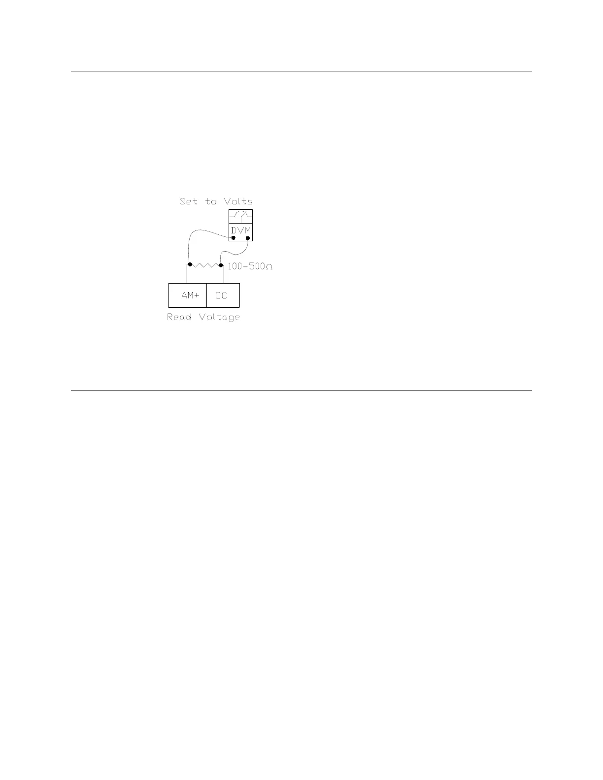
To read Voltage at this terminal, connect a 100 – 500 resistor from AM (+) to
CC. The voltage is read across the 100 – 500 resistor.
AM Terminal Setup Parameters
F670 — Set AM Function
F671 — Calibrate AM Terminal
F685 — Output Response Polarity Selection
F686 — Set Zero Level
Direct Access Number — F670
Parameter Type — Selection List
Factory Default — Output Frequency
Changeable During Run — Yes
AM Output Terminal Adjustment
Program Ter mi nal Analog Output Terminals
This parameter is used to calibrate the AM analog output.
To calibrate the AM analog output, connect an ammeter as described at F670.
When the ASD is running at a known value (e.g., output frequency), adjust this
parameter until the associated function of
F670 produces the desired DC level
output at the AM output terminal.
See F670 for additional information on this parameter.
Direct Access Number — F671
Parameter Type — Numerical
Factory Default — 512
Changeable During Run — Yes
Minimum — 1
Maximum — 1280
F670 F671

 Loading...