Do you have a question about the Toshiba RAS-10KHP-E3 and is the answer not in the manual?
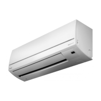
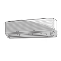
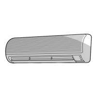
Diagrams and dimensions detailing the indoor unit's construction and mounting.
Diagrams and dimensions for specific outdoor unit models: RAS-13/10UAH-E3, RAS-13/10UA-E3, RAS-13/10UAX3, RAS-12UAX3.
Diagrams and dimensions for specific outdoor unit models: RAS-07UAH-E3, RAS-07UA-E3, RAS-07UAX3.
Wiring diagram for the RAS-13UKHP-E3 and RAS-13UAH-E3 models.
Wiring diagram for the RAS-10UKHP-E3 and RAS-10UAH-E3 models.
Wiring diagram for the RAS-07UKHP-E3 and RAS-07UAH-E3 models.
Wiring diagram for the RAS-13UKP-E3 and RAS-13UA-E3 models.
Wiring diagram for the RAS-10UKP-E3 and RAS-10UA-E3 models.
Wiring diagram for the RAS-07UKP-E3 and RAS-07UA-E3 models.
Electrical parts specifications for indoor units RAS-13/10/07UKHP-E3.
Electrical parts specifications for outdoor unit RAS-13UAH-E3.
Electrical parts specifications for outdoor unit RAS-10UAH-E3.
Electrical parts specifications for outdoor unit RAS-07UAH-E3.
Electrical parts specifications for indoor units RAS-13/10/07UKP-E3 and RAS-13/10/12/07UKPX3.
Electrical parts specifications for outdoor unit RAS-13UA-E3.
Electrical parts specifications for outdoor units RAS-13UAX3 and RAS-12UAX3.
Electrical parts specifications for outdoor unit RAS-10UA-E3.
Electrical parts specifications for outdoor unit RAS-07UAX3.
Electrical parts specifications for outdoor unit RAS-07UA-E3.
Refrigeration cycle diagram for RAS-13UKHP-E3 / RAS-13UAH-E3 models.
Refrigeration cycle diagram for RAS-10UKHP-E3 / RAS-10UAH-E3 models.
Refrigeration cycle diagram for RAS-07UKHP-E3 / RAS-07UAH-E3 models.
Refrigeration cycle diagram for RAS-13UKP-E3 / RAS-13UA-E3 models.
Refrigeration cycle diagram for RAS-10UKP-E3 / RAS-10UA-E3 models.
Refrigeration cycle diagram for RAS-07UKP-E3 / RAS-07UA-E3 models.
Control block diagram for specific heat pump models.
Control block diagram for various other air conditioner models.
Explains the overall control logic of the air conditioner system.
Details the control mechanism for the vertical air flow louver.
Explains the operation and speed control of the indoor fan motor.
Details the operational circuits and their functions.
Describes the unit's operation when set to fan-only mode.
Details the control logic and operation during cooling mode.
Details the control logic and operation during dry mode.
Details control logic for heating operation (heat pump models).
Explains the function and operation of the Hi POWER mode.
Controls to prevent excessive pressure in heat pump models.
Controls to prevent freezing of the indoor heat exchanger.
Operation to remove ice during heating (heat pump models).
Controls to prevent exceeding current limits (heat pump models).
Functionality for automatic restart after power interruption.
Indicates when the air filter requires cleaning.
Function to reduce indoor humidity and prevent mold.
Important safety precautions and warnings for the installation process.
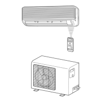
Visual guide illustrating the installation layout of indoor and outdoor units.
Details regarding installation procedures and components.
Procedures and guidelines for installing the indoor unit.
Guidelines and considerations for installing the outdoor unit.
Instructions for setting the remote control selector switch.
Covers additional installation topics such as gas leak tests and test operations.
General steps and guidelines for troubleshooting unit issues.
Fundamental checks to perform before advanced troubleshooting.
Initial assessment and diagnosis of common operational problems.
Using the remote control for self-diagnosis and interpreting check codes.
Diagnostic flowcharts for various operational issues.
Troubleshooting steps related to the remote control and indoor PC board.
Procedures for replacing various parts within the indoor unit.
Procedures for replacing various parts within the outdoor unit.
Exploded view and parts list for the indoor unit (heat pump model).
Exploded view and parts list for the indoor unit (cooling model).
Detailed exploded view and parts list for the indoor unit.
Exploded view and parts list for the RAS-13UAH-E3 outdoor unit.
Exploded view and parts list for the RAS-10UAH-E3 outdoor unit.
Exploded view and parts list for the RAS-13UA-E3 outdoor unit.
Exploded view and parts list for the RAS-10UA-E3 outdoor unit.
Exploded view and parts list for RAS-13UAX3 and RAS-12UAX3 outdoor units.
Exploded view and parts list for the RAS-10UAX3 outdoor unit.
Exploded view and parts list for RAS-07UAX3 and RAS-07UA-E3 outdoor units.
Exploded view and parts list for the RAS-07UAH-E3 outdoor unit.
| Type | Split System |
|---|---|
| Heating Capacity | 3.2 kW |
| Power Supply | 220-240V, 50Hz |
| Refrigerant | R410A |
| Indoor Unit Weight | 9 kg |
| Noise Level (Outdoor) | 50 dB(A) |