4.7 Driver Board for G2+2270 through G2+2330 and
G2+4270 through G2+430K
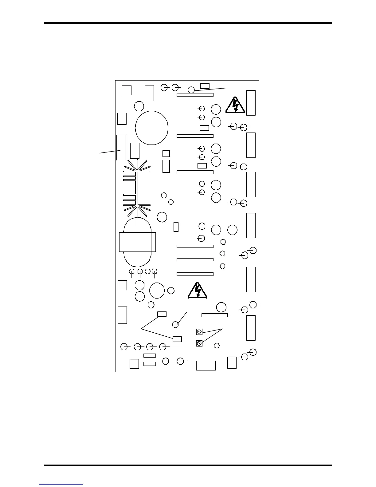
The following pictorial shows a layout of the major components located on the
driver board 35589/VT3D-2039
4 - 10
TOSHIBA
CN91
CN3A
CN71
CN11
CN5A
CN6A
J21
CN2A
FUSE
AC250V
1A
Charge
LED 21
22RH
21RH
CN21 CN61 CN41 CN51
CN31
J4
Do Not
Adjust
Do Not
Adjust
CN1A
Power
LED 1
Note:
1) Potentiometer 21RH (OP) is the main circuit overvoltage detection trip set. This
adjustment is factory set and any ADJUSTMENT BY THE USER SHOULD NOT BE
ATTEMPTED.
2) Potentiometer 22RH (MUV) is the main circuit undervoltage detection trip set. This
adjustment is factory set and any ADJUSTMENT BY THE USER SHOULD NOT BE
ATTEMPTED.
3) Do not adjust J4 and J21.
5) Charge LED indicates charged capacitors. DO NOT TOUCH internal parts if lighted.