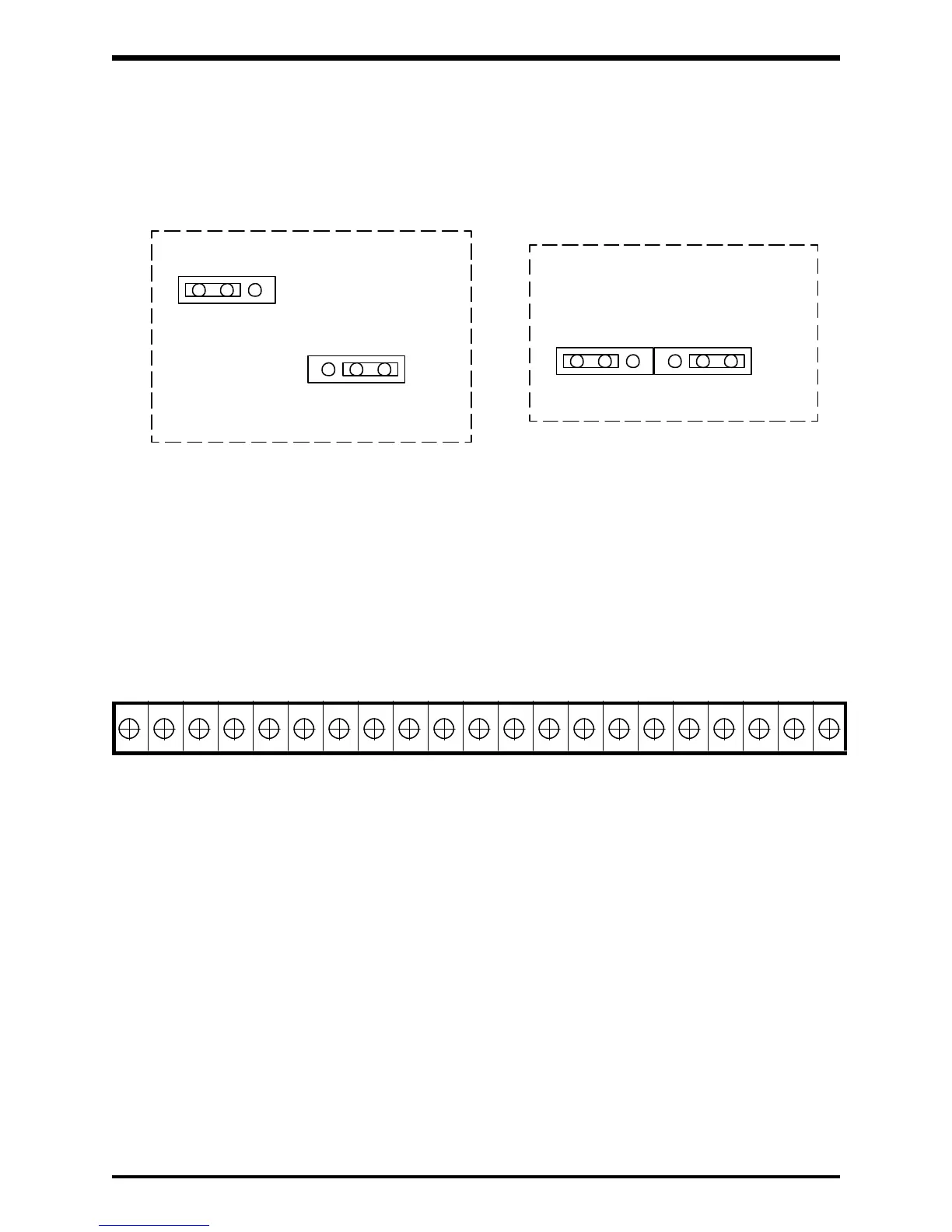
4.8 Jumper Details
The jumper connections for each of the printed wiring boards on Pages 4-7 through
4-9 are shown in the enlarged details below. Only jumpers JP1 and JP2 should be
adjusted by the user. See Page 8-12 for jumper adjustments.
4 - 11
JP2
JP1
VI
10V 5V
TOSHIBA
Detail 1 (Reference pages 4-7 and 4-8)
JP2
JP1
I V 10V 5V
Detail 2 (Reference page 4-9)
4.9 Control/Driver Board Terminal Block Details
The control/driver board terminal block is shown in detail below. Each of the twenty-one
terminals is functionally labeled. See Pages 4-12 and 4-13 for a list of terminal functions.
See sections 8.4, 8.5, and 8.6 for terminal connection applications.
CCRST
AD2JOG
(SS2) (SS3)
FMFLA P24FLCFLB PPAM
LOWRCH
(UL)
(LL)
RR IV CC ST F R CC SSI
Control/Driver Board Terminal Block Detail (Reference pages 4-7, 4-8, and 4-9)