TOSHIBA
7.5 Status Monitoring
The inverter's current status conditions can be monitored at any time while in the
monitor mode. In addition, if the inverter were to trip, the status conditions which
existed at the time of the trip could also be monitored. This is provided that monitoring
is performed before resetting the inverter.
7.5.1 Normal Status Monitoring
The following two tables give examples of what could possibly be seen under
normal conditions. The second table illustrates additional conditions which can
be monitored by pressing the NEXT key.
7 - 6
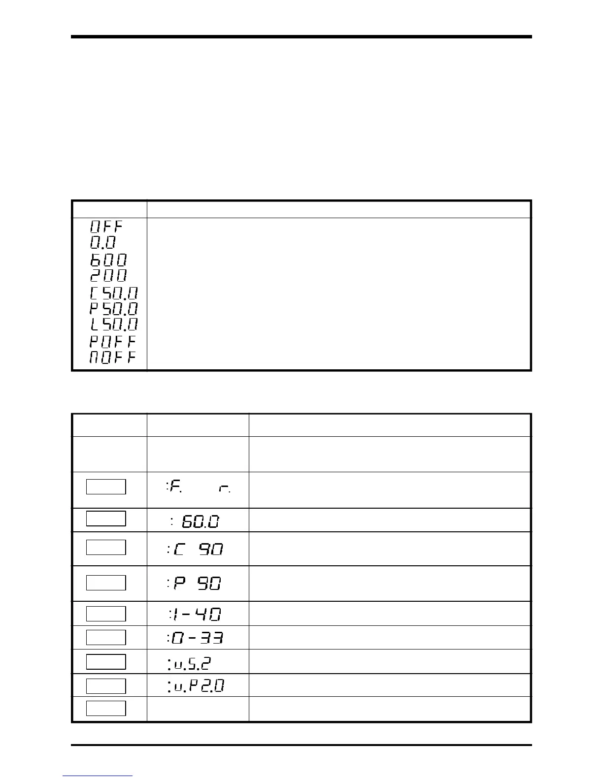
Key Display Status
Assume the unit is in the monitor mode and not the
function mode.
Indicates a forward (F) or reverse (r) run. If not running,
the display refers to the direction the unit would run.
Displays the inverter's set output frequency.
The inverter's output current is 90% (90% of the inverter's
rated output current).
The inverter's output voltage is 90% (90% of the inverter's
rated output voltage).
Input terminal status code. See section 7.5.3
Output terminal status code. See section 7.5.4
Inverter's software version
Keypad's software version
Returns to the original display.
NEXT
NEXT
or
NEXT
NEXT
NEXT
NEXT
NEXT
NEXT
NEXT
Power supply undervoltage (The input voltage supplied to the inverter is too low).
Stall prevention activated *
Overload detection activated *
0Hz (ready to run with ST-CC shorted)
Display Status
Not ready for run (with ST-CC opened)
60.0Hz (running at 60.0Hz)
200Hz (running at 200Hz)
Overvoltage limitation activated *
DC main circuit undervoltage (The inverter's internal DC main voltage is too low).
* Displays a flashing C, P, and L
Normal Monitoring
Additional Normal Monitoring