tousek / E_PULL-T24-T24speed_49002410 / 06. 08. 2019 - 17 -
•
Connection and detailed information of radio transmission system TX 310 see according manual.
•
Connection and detailed information of inductive system TX 400i see according manual.
G
Main safety edge (terminals 50/52) Safety
active: to be selected if the contact strip (8,2kOhm) of main safety sensing edge should be evaluated.
radio edge TX: to be selected if safety sensing edge (8,2kΩ) of main entrance edge should be evaluated with the
radio transmission system TX 310.
TX 400: to be selected if safety sensing edge (8,2kΩ) of main entrance edge should be evaluated with the system
TX 400i.
not active: to be selected if the contact strip of main safety sensing edge should NOT be evaluated
G
Side safety edge (terminals 50/51) Safety
active: to be selected if the contact strip (8,2kOhm) of side safety sensing edge should be evaluated.
radio edge TX: to be selected if safety sensing edge (8,2kΩ) of side entrance edge should be evaluated with the
radio transmission system TX 310.
TX 400: to be selected if safety sensing edge (8,2kΩ) of side entrance edge should be evaluated with the system
TX 400i.
not active: to be selected if the contact strip of side safety sensing edge should NOT be evaluated.
Safety sensing edges (main and side edge)
• OBSTACLE DETECTION: when a contact strip is
triggered/activated then a change of direction is
eected for 1 second. Then the gate stops.
Hence if: safety edges that have to react on obstacles in closing movement have to be serially connected
to the terminals of the main safety edge.
Safety edges that have to react on obstacles in opening movement have to be serially connected
to the terminals of the side safety edge.
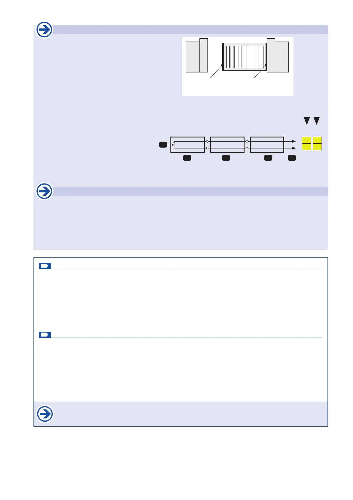
Example: W 8,2kΩ nal resistance
1 nal edge
2+3 passage edge
S to control board
When connecting one safety edge a nal edge (1) has to be used.
Side safety sensing edge
Function:
safety during opening
Main safety sensing edge
Function:
Safety during closing
1
W
2 3 S
50
52
50
51
Main safety sensing edge
Side safety sensing edge
Important
• After giving the impulse to program the end positions, no other impulse must be given. Also the safety devices
mustn´t be triggered. This would lead to an interruption of the programming process.
• Therefore, the mechanical stops must be set so that the existing contact strips cannot be triggered.