tousek / EN_PULL-T8-T10-T15-M-S_02 / 25. 03. 2020 - 27 -
7. Optional DIN rail
M
Sliding gate operator PULL T8, -T10, -T15 / Master-Slave
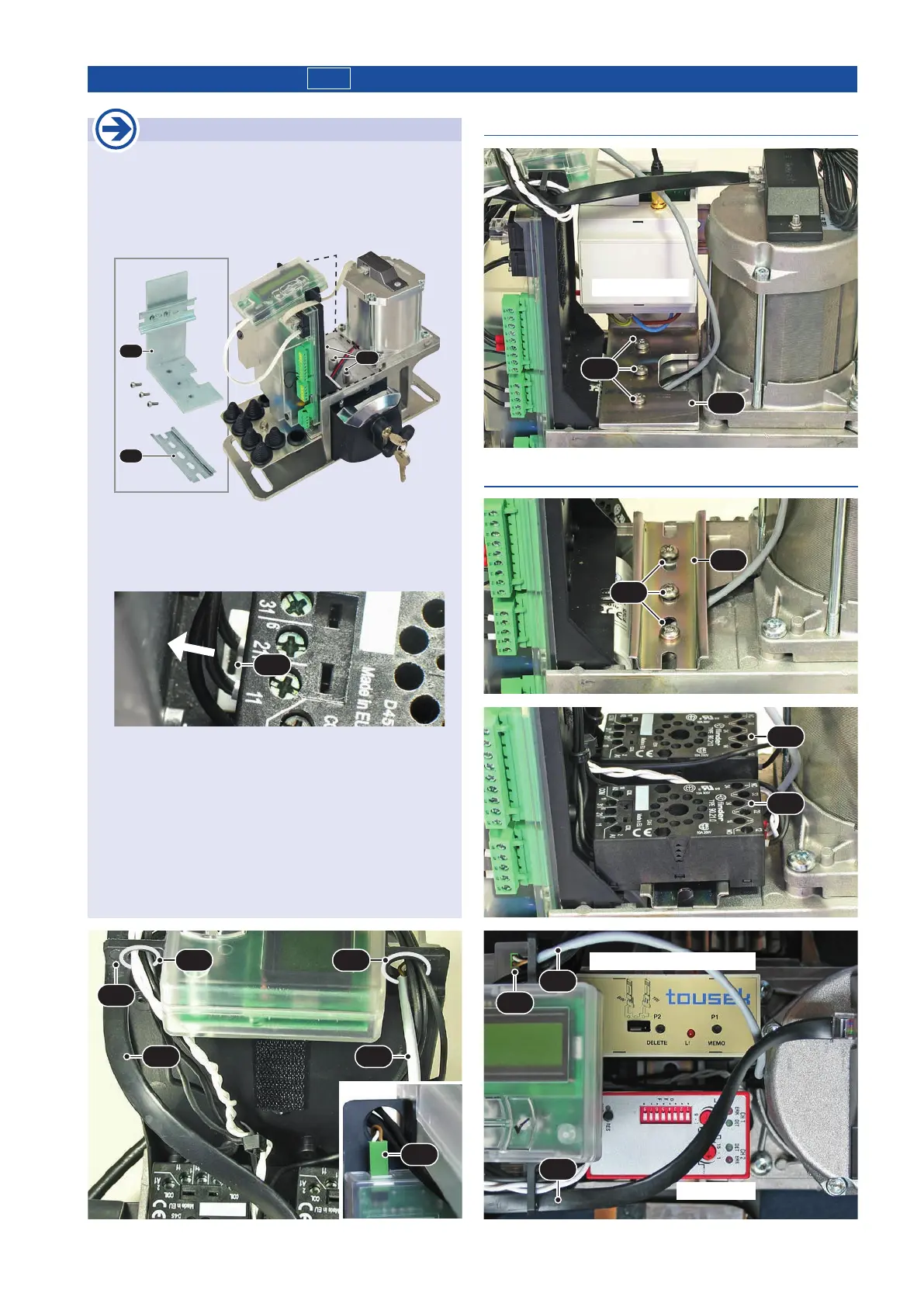
Mounting of additional equipment
•
Depending on the accessory either the DIN rail (H)
or the angle with DIN rail (W) can be be used, the
xation in the drive takes place with three screws at
the positions (P). Among others, e.g. devices with
socket for DIN rail mounting are suitable able.
W
H
P
• The pre-wired connectors (SO) are xed by gently
pressing on the DIN rail. To remove a plug socket (con-
nector) from the DIN rail, pull the locking lever(V) with
a screwdriver or similar.
V
•
Proceed carefully for cable routing. Never lay the cables
so that that they get damaged when mounting the opera-
tor cover. For conducting the cable enlarge the existing
hole (B1) or make a new hole/driling (B2).
•
Finally, make sure that the sensor cable (S) is in
their respective guides (F) and that the plug-comb
(SK) of emergency release cable (N) is connected to
the control board
!
H
DIN rail without angle: e.g. with ISD and BT40-SO
SK
S N
F
B2 B1
e.g. ISD 5/2
e.g. receiver BT40-SO
SK
N
S
Angle with DIN rail: e.g. with GSM 400
P
W
e.g. GSM 400
P
SO
SO