tousek / EN_PULL-T8-T10-T15-M-S_02 / 25. 03. 2020 - 9 -
3.1 Terminal assignment Sliding gate operator PULL T8, -T10, -T15 / Master-Slave
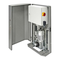
Grounding
The grounding connection is made on the operator
housing with the designated grounding screw!
see gure page 8
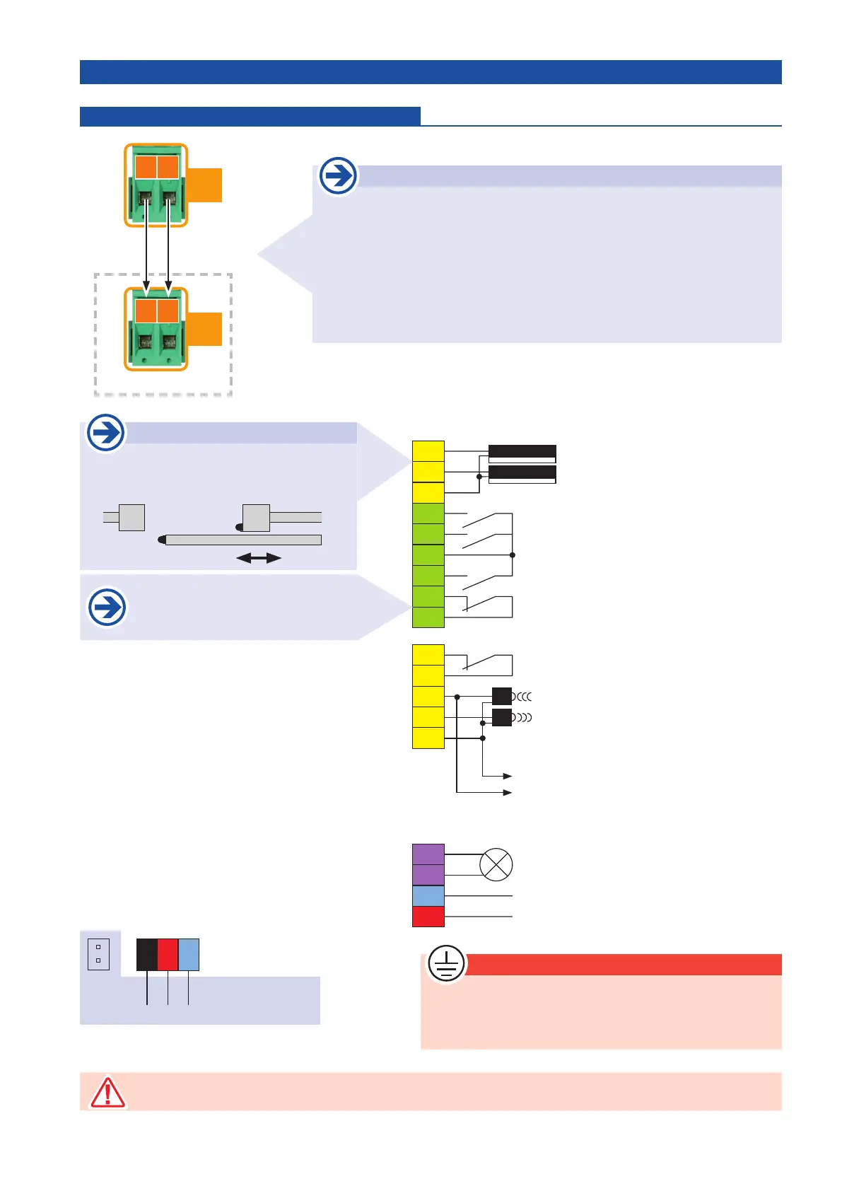
Signal lamp 230V, 100W
Power supply 230V a.c.
Contact for photocells
Common photocell contact
Power supply photocell receiver
Power supply photocell transmitter
Power supply common photocell
Main safety edge
Side safety edge
Common contact safety edge
Pedestrian - switch
CLOSE - switch
common
impulse - switch
STOP - contact
Power supply
max. 24Va.c., 5W
40
41
43
45
46
31
37
32
30
33
34
52
51
50
1
2
10
11
85
84
86
24V
~
L
N
8.k2
8.k2
L
N
black
Motor connection
red
230V a.c.
blue
pre-wired
Motor condenser
24V
~
Master control unit Terminal assignment
The stop input has no emergency stop function! - In order to ensure the emergency stop function, provide
the supply line with an all-pole disconnecting emergency stop switch, that locks after actuation!
Safety sensing edges
Function main safety sensing edge (MCE):
Safety during closing
Function side safety sensing edges (SE):
Safety during opening
MCE
SE
CLOSE OPEN
If no stop switch is connected, termi-
nals 31/37 have to be wire-bridged.
Connection Master /Slave control unit
• For the connection of the master and slave control unit connect the
terminals 88 and 89 in the system connector to each other.
• Max. cable length between the operators: 25m.
• Cable type e.g.: PVC control cable YSLY 2 x1mm
2
or equivalent.
88
89
B
SLAVE control unit
88
89
B
High
Low
Bus system