tousek / EN_PULL-T8-T10-T15-M-S_02 / 25. 03. 2020 - 33 -
NOTE concerning cable laying
The electric cables have to be laid in insulating
sleeves which are suitable for underground us-
age. The insulating sleeves have to be lead into
the inner of the operator housing.
230 V cables and control lines have to be laid in
separate sleeves.
Only double-insulated cables, which are suitable
for underground usage (e.g. E-YY-J) may be used.
In case that special regulations require another
type of cable, cables according to these regula-
tions have to be used.
SAFETY NOTE
Please be aware that the beside picture is only a
symbolic sample illustration of a gate facility and may
therefore not show all safety devices required for your
specic application.
To achieve an optimum safety level at your gate facil-
ity, please make sure that all safety components and
accessories which - according to the applying safety
rules and laws - are required in your particular case
(e.g. photocells, induction loops, sensing edges, signal
lamps, trac lights, mains- and emergency power o
switches etc.) are properly installed, operated, and
serviced.
In this context please follow the EU Machine Directive,
accident prevention rules and laws, as well as apply-
ing EU- and national standards in force at the time of
installation and operation of the gate facility.
The Tousek Ges.m.b.H. cannot be held responsible
for any consequences resulting from disregard of
applying standards and laws during installation or
operation of the gate facility.
The 0,75mm
2
control lines are shown without
ground lead. In order to facilitate connections
we recommend using exible wires and not
using thicker wires for the control lines.
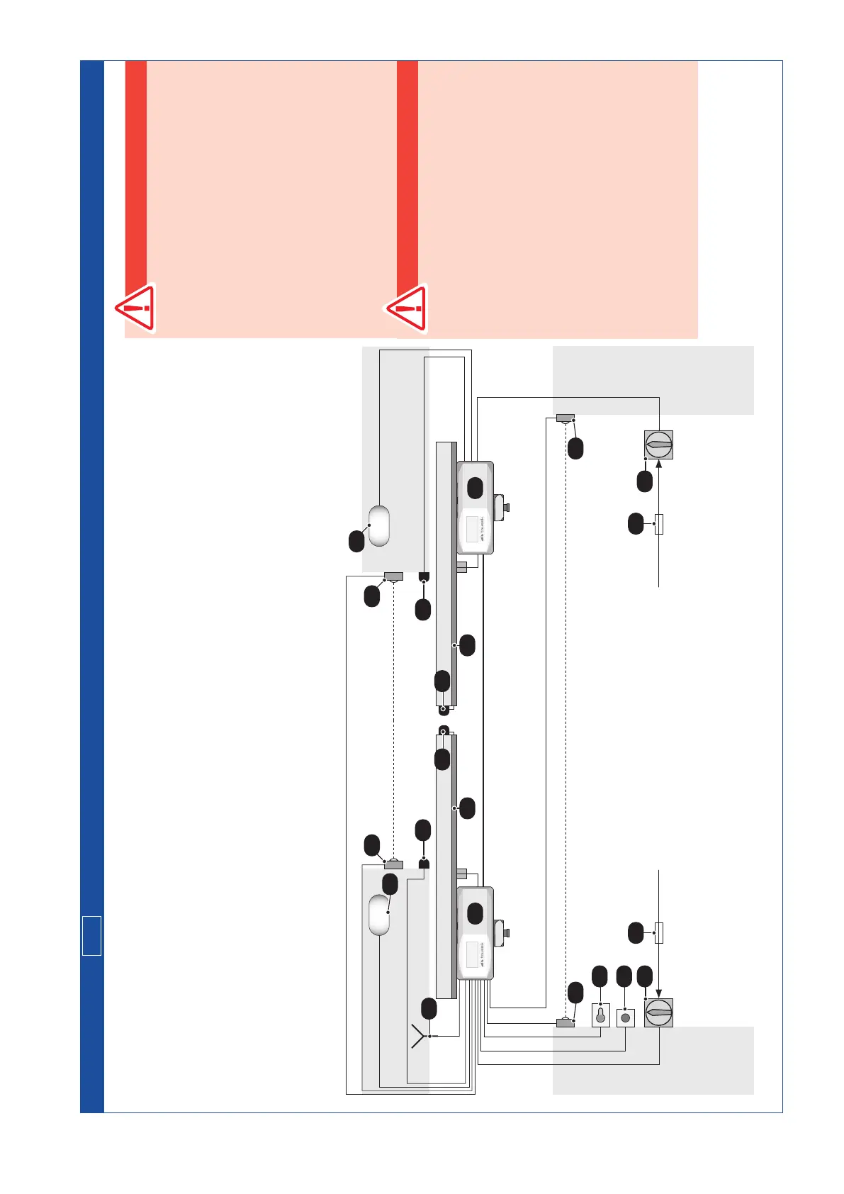
10. Cable plan
M/S
Sliding gate operator PULL T8, -T10, -T15 / Master-Slave
1
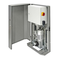
operator TOUSEK PULL T8, -T10, -T15 (M=Master, S=Slave)
2 outer photocell (s=transmitter, e=receiver)
3 inner photocell (s=transmitter, e=receiver)
4 antenna for integrated receiver
5 key contact switch
6 stop button
7 main switch 16A
Note:An all-pole disconnecting main switch with a
contact opening-gap of minimum 3 mm has to be
foreseen.
8 fuse 12A
9 safety sensing edge
(o=safety when opening, s=safety when closing)
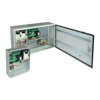
10 power supply sytem TX100
if you use a dierent system (e.g. TX200i or TX) see
corresponding instruction manual
11 signal ashing light
2 x 0,75
2
4 x 0,75
2
2 x 1,5
2
2 x 0,75
2
2 x 0,75
2
4 x 0,75
2
2 x 0,75
2
1M
2e 2s
3s 3e
4
5
6
3 x 1,5
2
3 x 1,5
2
4 x 0,75
2
7
8
9s
9o 9o
11
11
10
Coaxial-
cable
2 x 1,5
2
2 x 0,75
2
Bussystem: 2 x 1
2
8
7
9s
10
1S