For an individual switch, the following page is displayed.
Figure 14-14 Cluster Configuration for Individual Switch
The following entries are displayed on this screen:
switch.
14.4 Application Example for Cluster Function
Network Requirements
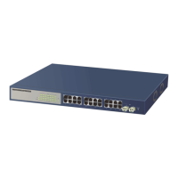
Three switches form cluster, one commander switch (Here take TP-LINK TL-SL5428E as an
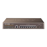
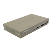
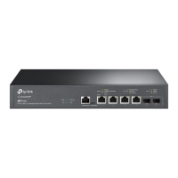
example) and two member switches (Here take TP-LINK
TL-SG3210/TL-SG3216/TL-SG3424/TL-SG3424P as an example). The administrator manages all
the switches in the cluster via the commander switch.
Port 1 of the commander switch is connecting to the external network, port 2 is connecting to
member switch 1 and port 3 is connecting to member switch 2.
IP pool: 175.128.0.1, Mask: 255.255.255.0.
232
 Loading...