MS-SVN084A-EN
13
Pipe Diameter inch (mm) Tightening Torque ft-lb (N-m)
Φ1/4 (6.35) 11.06 - 22.13 (15 - 30)
Φ3/8 (9.53) 25.82 - 29.5 (35 - 40)
Φ1/2 (12.7) 33.19 - 36.88 (45 - 50)
Φ5/8 (15.88) 44.25 - 47.94 (60 - 65)
Φ3/4 (19.05) 51.63 - 55.32 (70 - 75)
Φ7/8 (22.23) 59 - 62.69 (80 - 85)
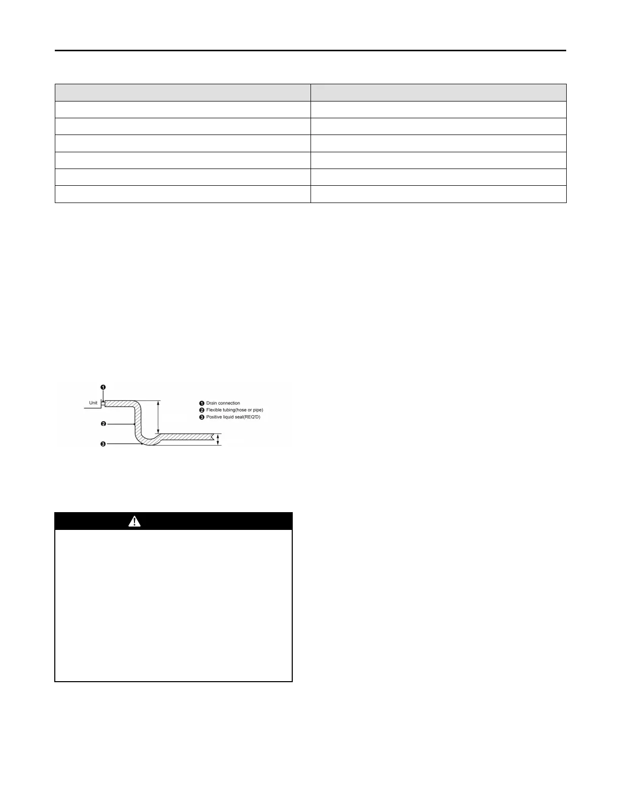
Condensate Removal
1. Condensate drain pipe should be connected into
special drain system for air conditioner.
2. The drain pan has primary and secondary drain
connection. Condensate removal is performed by
attaching a 3/4” PVC pipe to the evaporator coil pan
and terminated in accordance with local or state
Plumbing/HVAC codes. The installation must
include a “P” style trap that is located closely to the
evaporator coil. Do not over-tighten the drain
connection in order to prevent possible damage to
the evaporator drain pan. See the following figure
for details of a typical condensate line “P” trap.
2" (51 mm) minimum
3" (76 mm) minimum
Ductwork
This air handler is designed for a complete supply and
return ductwork system.
WWAARRNNIINNGG
SSAAFFEETTYY HHAAZZAARRDD!!
FFiieelldd dduuccttwwoorrkk mmuusstt mmeeeett tthhee NNaattiioonnaall FFiirree
PPrrootteeccttiioonn AAssssoocciiaattiioonn NNFFPPAA 9900AA,, NNFFPPAA 9900BB aanndd
aannyy aapppplliiccaabbllee llooccaall oorrddiinnaannccee.. SShheeeett mmeettaall
dduuccttwwoorrkk rruunn iinn uunnccoonnddiittiioonneedd ssppaacceess mmuusstt bbee
iinnssuullaatteedd aanndd ccoovveerreedd wwiitthh aa vvaappoorr bbaarrrriieerr..
FFiibbrroouuss dduuccttwwoorrkk mmaayy bbee uusseedd iiff ccoonnssttrruucctteedd aanndd
iinnssttaalllleedd iinn aaccccoorrddaannccee wwiitthh SSMMAACCNNAA
CCoonnssttrruuccttiioonn SSttaannddaarrdd oonn FFiibbrroouuss GGllaassss DDuuccttss..
DDuuccttwwoorrkk mmuusstt ccoommppllyy wwiitthh NNaattiioonnaall FFiirree
PPrrootteeccttiioonn AAssssoocciiaattiioonn aass tteesstteedd bbyy UU//LL SSttaannddaarrdd
118811 ffoorr CCllaassss II AAiirr DDuuccttss.. CChheecckk llooccaall ccooddeess ffoorr
rreeqquuiirreemmeennttss oonn dduuccttwwoorrkk aanndd iinnssuullaattiioonn..
• Duct system must be designed within the range of
external static pressure the unit is designed to
operate against. It is important that the system
airflow be adequate. Make sure supply and return
ductwork, grills, special filters, accessories, etc. are
accounted for in total resistance. See fan
performance data in this manual.
• Do not operate the unit without all ductwork
completed.
• Do not operate this product without all ductwork
attached.
• Inadequate ductwork that restricts airflow can result
in improper performance and compressor or heater
failure. Ductwork is to be constructed in a manner
that limits restrictions and maintains suitable air
velocity. Ductwork is to be sealed to the unit in a
manner that will prevent leakage.
• RReettuurrnn dduuccttwwoorrkk:: Do not terminate the return
ductwork in an area that can introduce toxic or
objectionable fumes/odors into the ductwork. The
return ductwork is to be introduced into the air
handler bottom (up flow configuration).
• RReettuurrnn AAiirr FFiilltteerrss:: Each installation must include a
return air filter. This filtering may be performed at
the air handler or externally such as a return air
filter grille.
Electrical Installation
RReeqquuiirreemmeenntt aanndd NNoottiiccee oonn EElleeccttrriiccaall IInnssttaallllaattiioonn
The electrical installation for the air handler should
observe the following requirements:
1. The electrical installation must be conducted by
trained personnel and done according to the
National Electric Code in addition to local rules and
regulations. The electric circuit must be equipped
with a circuit breaker with sufficient capacity.
2. The unit’s operating power must be within the
nominal range stated in the installation manual.
Use a dedicated power circuit for the air handler. Do
not draw power from another power circuit.
3. The air handler circuit should be at least 5 feet (1.5
m) away from any flammable surface.
4. Connect wiring by referring to the circuit diagram
labeled on the unit and securely tighten.
IInnssttaallllaattiioonn