116
AC-SVX003A-EN
Unit Wiring
The following table provides a list of electrical schematics,
field wiring diagrams and connection diagrams.
Wiring diagrams can be accessed via e-Library. A
laminated wiring diagram booklet is also shipped with each
unit.
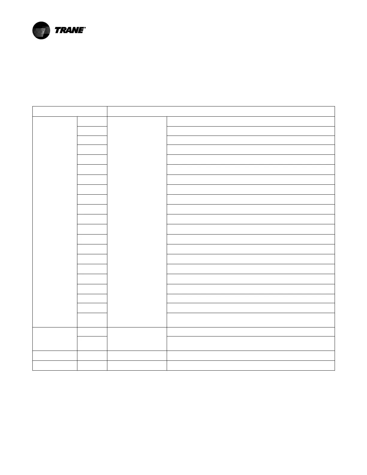
Table 33. Wiring diagrams — 150 to 330 ton units
Document Number
Description
2311-5991
Sheet 1
Schematic Wiring
Device Designations, Locations, and Warning
Sheet 2 Condenser Fan Locations
Sheet 3 Unit Power Distribution
Sheet 4
Compressor VFDs, Harmonic Filters, and Evaporator Pump Power Distribution
Sheet 5
Circuit 1 Variable Speed Condenser Fans (default)
Sheet 6
Circuit 2 Variable Speed Condenser Fans (default)
Sheet 7
Extra Free Cooling Fans (optional)
Sheet 8
Circuit 1 Fixed Speed condenser Fans (optional)
Sheet 9
Circuit 2 and Split V Fixed Speed Condenser Fans (optional)
Sheet 10
Compressor VFD Control and Options Enclosure Interface
Sheet 11
Compressor Control
Sheet 12
Refrigerant, Heater, and Common Panel Control
Sheet 13
115 VAC 27 VAC CPTS, 24 VDC Power Supplies, Flow Switch, and Oil Level Switches
Sheet 14
Variable Speed Condenser Fan Control Refrigerant Circuit 1 and 2 (default)
Sheet 15
Fixed Speed Condenser Fan Control Refrigerant Circuit 1 (optional)
Sheet 16
Fixed Speed Condenser Fan Control Refrigerant Circuit 2 and Shared V (optional)
Sheet 17
Free Cooling Bypass Actuators and Extra Free Cooling Fan Control
Sheet 18
Evaporator Pump Package (optional)
Sheet 19 Global Bus Connections
Sheet 20
Symbio 800 Connections
Sheet 21
Field Connections; 115 VAC/1 and 24 VDC, Convenience Outlet, Evaporator Heaters,
and I/O
2311–6454
Sheet 1
Field Wiring
Power and Communications Connections
Sheet 2
Field Connections; 115VAC/1 and 24 VDC, Convenience Outlet, Evaporator Heaters,
and I/O
5732–5331
Panel Component Location
5732–5333
Unit Component Location

 Loading...


