AC-SVX003A-EN
69
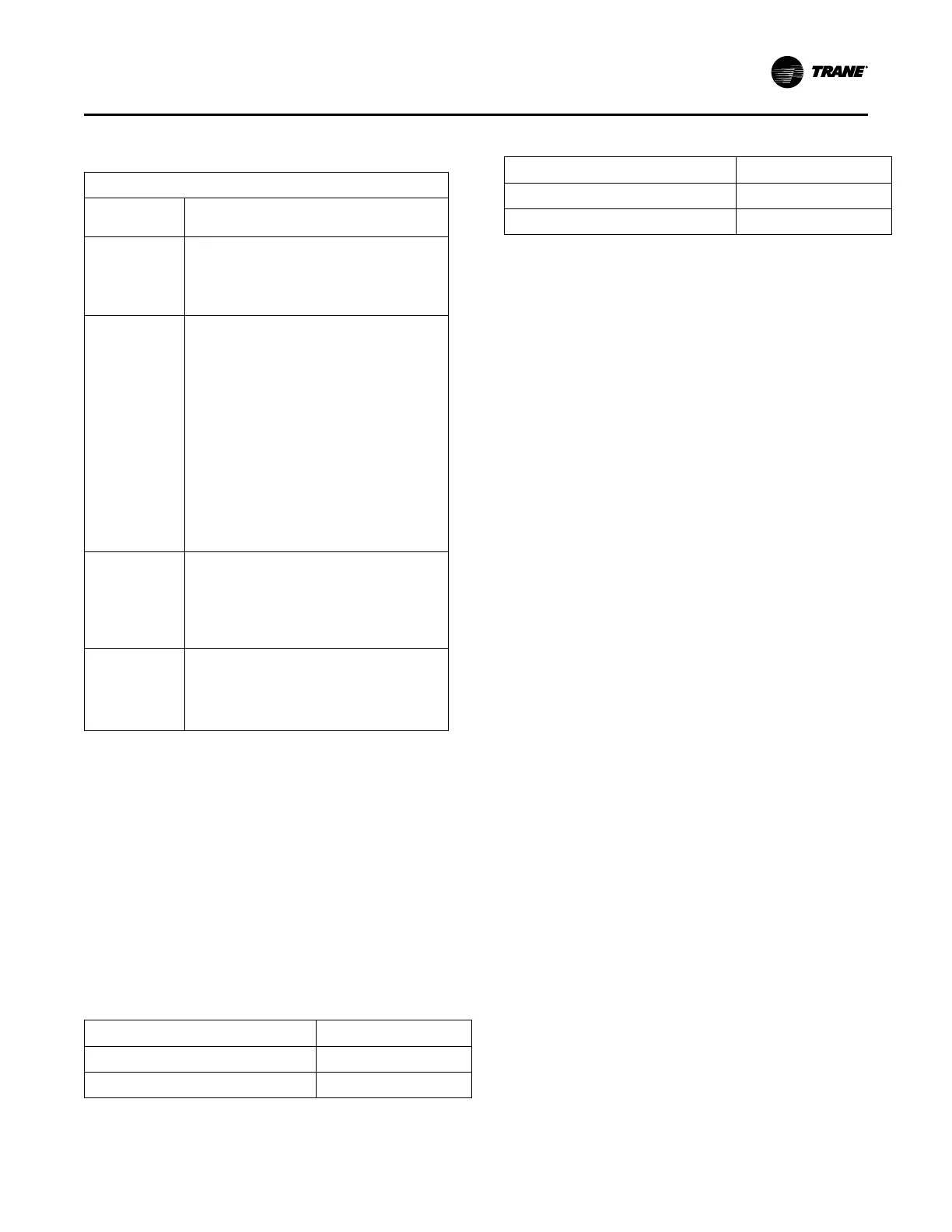
Table 25. Alarm and status relay output
configurations (continued)
Description
Circuit 2
Running
The output is true whenever any compressor of
Circuit 2 is running.
Maximum
Capacity
The output is true whenever the unit has reached
maximum capacity continuously for the Max
Capacity Relay debounce time. The output is false
when the unit is not at maximum capacity
continuously for the filter debounce time.
Evaporator Water
Freeze
Avoidance
Request
This relay output is energized any time either the
Low Evaporator Water Temperature – Unit Off or
the Low Evaporator Temperature Ckt x – Unit Off
diagnostics are active. This relay is intended for use
as an external interlock for a field engineered and
provided solution to mitigate the freeze danger
implied by these diagnostics. Generally, this would
be used in cases where operation of the evaporator
water pump is unacceptable due to the system
constraints, (i.e. such as mixing unconditioned
warm water with controlled supply water as
provided by other parallel chillers. The relay’s
output can provide the method to close bypass
valves so the circulation becomes local to the evap
and excludes the load, or can be used to defeat the
evap pump override entirely while initiating an
independent source of heat / flow to the evap.
Free-Cooling
Status
The output is true (closed) whenever Free Cooling
is active and the capacity is > 0%. The output is
false (open) whenever Free Cooling is inactive or
capacity = 0%.
Note: Free-cooling option is not available on all
sizes.
Free-Cooling
Maximum
Capacity
The output is true (closed) whenever Free Cooling
capacity – 100%. The output is false (open)
whenever Free Cooling is 100% capacity.
Note: Free-cooling option is not available on all
sizes.
Relay Assignments Using
Tracer® TU
Tracer®TU Service Tool is used to install the
Programmable Relay Option package and assign any of
the above list of events or status to each of the four relays
provided with the option. (See Tracer® TU section of
Controls chapter for more information on this service tool.)
The relays to be programmed are referred to by the relay’s
terminal numbers on the Programmable Unit Status LLID
board.
The default assignments for the four available relays of the
Programmable Relay option are show in the table below.
Table 26. Default assignments
Relay Assignment
Relay 1 Terminals J2-1,2,3:
Unit Limit Mode
Relay 2 Terminals J2-4,5,6: Maximum Capacity
Table 26. Default assignments (continued)
Relay Assignment
Relay 3 Terminals J2 - 7,8,9: Compressor Running
Relay 4 Terminals J2 -10,11,12:
Alarm
If any of the Alarm/Status relays are used, provide
electrical power, 115 VAC with fused-disconnect to the
panel and wire through the appropriate relays (terminals on
the LLID board). Provide wiring (switched hot, neutral, and
ground connections) to the remote annunciation devices.
Do not use power from the chiller’s control panel
transformer to power these remote devices. See the field
wiring diagrams which are shipped with the unit.
Low Voltage Wiring
The remote devices described below require low voltage
wiring. All wiring between these remote input devices and
the control panel must be made with shielded, twisted pair
conductors. Ground the shielding only at the panel.
Important: The remote devices described in this section
require low voltage wiring. All wiring between
these remote input devices and the control
Panel must be made with shielded, twisted
pair conductors. Ground the shielding only at
the panel.
Emergency Stop
The unit controller provides auxiliary control for a customer
specified/installed latching trip out. When this customer-
furnished remote contact is provided, the chiller will run
normally when the contact is closed. When the contact
opens, the unit will trip on a latching diagnostic. This
latched condition requires either a manual reset at the front
of the control panel or a power cycle of the unit controller to
clear.
Connect low voltage leads to Emergency Stop terminal
strip locations on External Auto-Stop and Emergency Stop
Inputs LLID board. Refer to the field diagrams that are
shipped with the unit.
Silver or gold-plated contacts are recommended. These
customer-furnished contacts must be compatible with 24
VDC, 12 mA resistive load.
External Auto/Stop
If the unit requires the external Auto/Stop function, the
installer must provide leads from the remote contacts to the
External Auto-Stop terminals of the External Auto-Stop and
Emergency Stop Inputs LLID board in on the control panel.
The chiller will run normally when the contacts are closed.
When either contact opens, the compressor(s), if operating,
will go to the RUN:UNLOAD operating mode and cycle off.
Unit operation will be inhibited. Closure of the contacts will
permit the unit to return to normal operation.
Installation Electrical

 Loading...


