96
AC-SVX003A-EN
c. Spray nozzle should be approximately 1 to 3 inches
from the coil surface.
d. Use at least a 15º fan type of spray nozzle.
Note: To avoid damage from the spray wand contacting the
coil, make sure the 90º attachment does not come in
contact with the tube and fin as abrasion to the coil
could result.
Cleaning the Evaporator
Because the evaporator is typically part of a closed circuit,
it does not accumulate appreciable amounts of scale or
sludge with properly treated working fluids. However, if
cleaning is deemed necessary, chemical and mechanical
means are both acceptable. If using chemical means, any
and all materials used in the external circulation system,
the quantity of the solution, the duration of the cleaning
period, and any required safety precautions should be
approved by the company furnishing materials or
performing the cleaning. When using mechanical means,
care must be taken in selecting the cleaning method and
equipment, as well as appropriate brush type and size if
used. The evaporator utilizes highly enhanced tubes which
can be damaged by some cleaning methods, resulting in a
loss of system performance.
In particular, evaporators in units larger than 300 nominal
tons may be equipped with a highly enhanced "micro"
structure that will not behave like a typical helical structure
when cleaned mechanically. This may require specialized
equipment or methods to force tube cleaning heads
through the tubes. In these instances, determination of
brush/head type and size is critical, as using an oversized
brush/head may damage the tube enhancement, while
using a brush/head that is too small could result in
incomplete cleaning.
Pump Package
Pumps not immediately placed into service, or removed
from service and stored, must be properly prepared to
prevent excessive rusting.
• Pump port protection plates must not be removed until
the pump is ready to connect to the piping.
• Rotate the shaft periodically (at least monthly) to keep
rotating element free and bearings fully functional.
• For long term storage (3 months or longer), prevent
internal rust buildup and possibility of freezing by
performing the following steps:
– Remove the casing plugs.
– If water is to be drained:
• Disconnect evaporator and piping heaters.
• Drain or blow out all water.
– As an optional step, it is acceptable to rustproof or
pack the casing with moisture absorbing material
and cover the flanges.
When returning pumps to service.
• Remove drying agent from the pump, if used.
• Reinstall casing plugs.
• If water had been drained:
– Refill water.
– Reconnect evaporator and piping heaters.
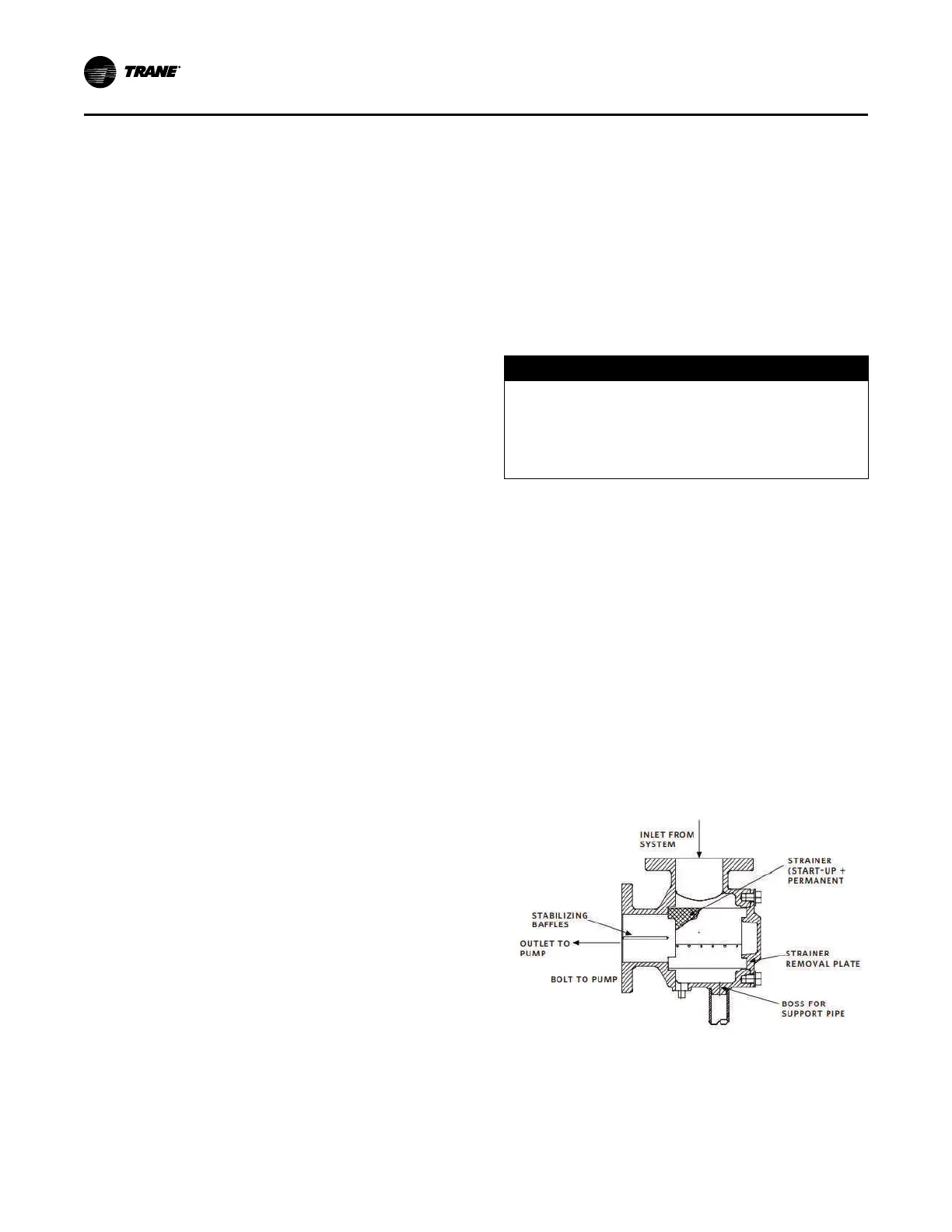
A blow–down valve may be installed on the Suction Guide
drain connection. Suction Guides are supplied with an inlet
tapped gauge connection. Monitoring the differential
pressure across the fitting, from the suction guide inlet
gauge to the pump inlet gauge, will alert the operator
should the strainer need to be removed and cleaned.
NOTICE
Equipment Damage!
Failure to follow instructions below could result in
equipment damage.
The factory installed temporary fine–mesh start-up
strainer must be removed following system clean up.
After all debris has been removed from the system, or a
maximum of 24 running hours, stop the pump and close the
pump isolation valves. Drain the Suction Guide by
removing the drain plug or opening the blowdown valve, if
installed. Remove the Suction Guide cover and remove the
strainer assembly from the valve body. A temporary fine–
mesh start-up strainer is tack–welded to the permanent
stainless steel strainer. This temporary strainer should now
be removed from the permanent strainer. The fine–mesh
strainer is designed to remove small particulate from new
piping systems and could easily clog with debris if left in
place. This will be detrimental to the operation of the pump.
Replace the permanent strainer into the fitting body, once
the temporary strainer is removed. Inspect the cover O–
ring and replace if necessary. Replace the cover into the
body. Ensuring that the strainer is properly seated, tighten
the cover bolts diagonally, evenly and firmly.
Figure 41. Pump package
Maintenance

 Loading...


