AC-SVX003A-EN
67
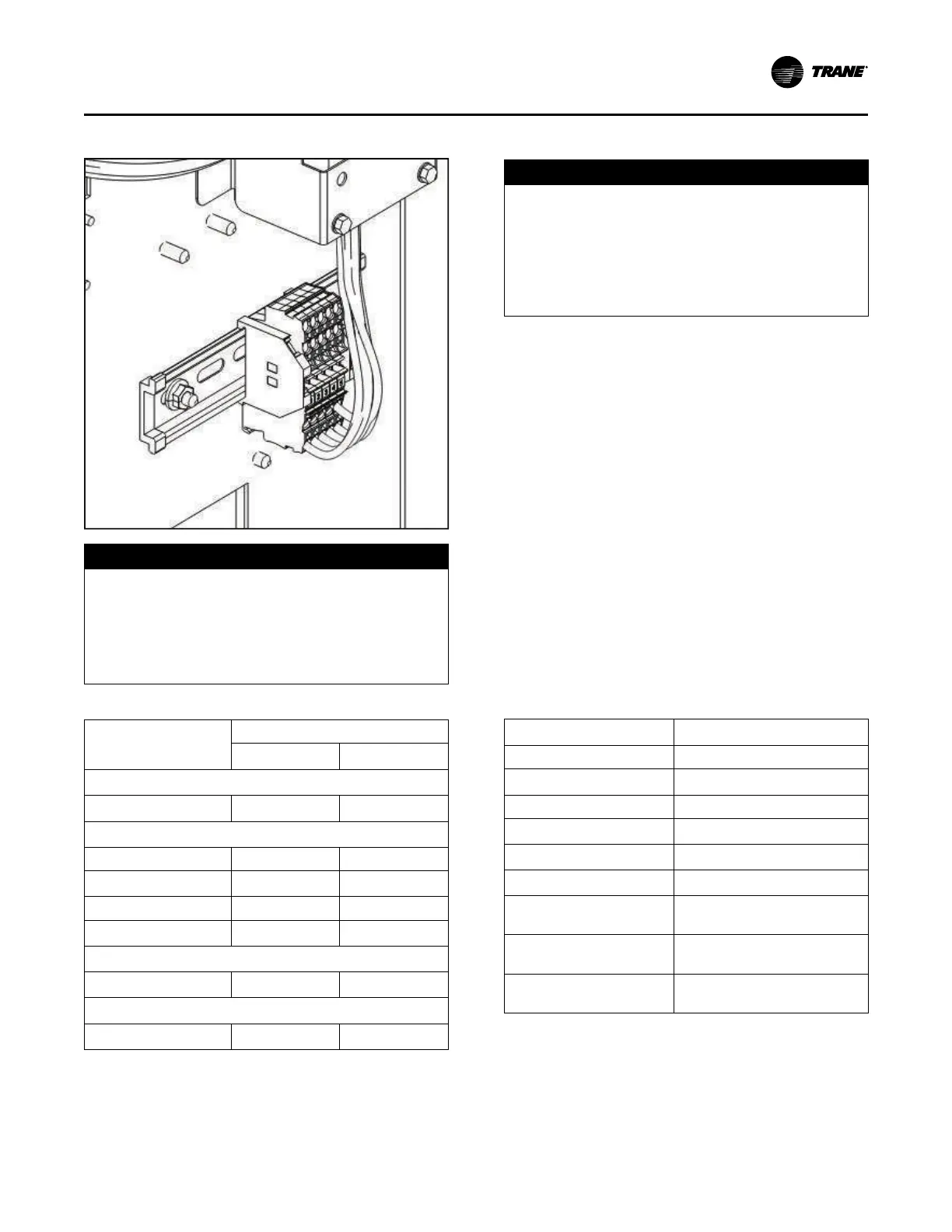
Figure 23. Evaporator heater view
NOTICE
Evaporator Damage!
Failure to follow instructions below could result in
evaporator damage.
A qualified technician must confirm operation of the
thermostat. Control panel main processor does not
verify thermostat operation.
Table 23. Factory installed water heater summary
Unit Size (tons)
Waterboxes
Supply
Return
1–pass Evaporator
Units larger than 300 tons 400W (Qty 2) 400W (Qty 2)
2-pass Evaporator
150 to 165 400W 400W
180 to 200
400W (Qty 2)
400W
225 to 330 600W 600W
Units larger than 330 tons 400W (Qty 2) 400W (Qty 2)
3-pass Evaporator
All sizes
400W (Qty 2)
400W
Factory Installed Pump Package
(a)
275 to 300
300W (Qty 4)
1200W
(a)
These heaters are in addition to the evaporator waterbox heaters.
Chilled Water Pump Control
NOTICE
Evaporator Damage!
If the microprocessor calls for a pump to start and
water does not flow, the evaporator may be damaged
catastrophically.
It is the responsibility of the installing contractor and/
or the customer to ensure that a pump will always be
running when called upon by the chiller controls.
An evaporator water pump output relay’s normally-open
contact closes to start the evaporator water pump when the
chiller is given a signal to go into the Auto mode of
operation from any source. The contact is opened to turn
off the pump in the event of most machine level diagnostics
to prevent the build up of pump heat.
The relay output is required to operate the Evaporator
Water Pump (EWP) contactor. The relay’s contacts are
compatible with 115/240 VAC control circuits. See
Programmable Relays section for rating details. Normally,
the EWP relay follows the AUTO mode of the chiller.
Whenever the chiller has no diagnostics and is in the
AUTO mode, regardless of where the auto command is
coming from, the relay is energized and the normally-open
contact is closed. When the chiller exits the AUTO mode,
the relay’s normally-open contact is timed to open in an
adjustable (using Tracer® TU service tool) 0 to 30 minutes.
The non- AUTO modes in which the pump is stopped,
include Reset, Stop, External Stop, Remote Display Stop,
Stopped by Tracer®, Start Inhibited by Low Ambient Temp,
and Ice Building complete.
Table 24. Pump relay operation
Chiller Mode
Relay Operation
Auto Instant Close
Ice Building
Instant Close
Tracer® Override Close
Stop Timed Open
Ice Complete Instant Open
Diagnostics Instant Operation
(a)
Chiller Shutdown Diagnostics
(except freeze protection)
Instant Open
Freeze Protection related chiller
shutdown diagnostics
Initially: Remain Closed
Then: Delayed/Dependent Open
Chiller Off Cycle Freeze
Diagnostics
Instant Close – Dependent Open
(a)
Operation can be instant open or instant close, depending on diagnostic.
When going from Stop to Auto, the EWP relay is energized
immediately. If evaporator water flow is not established in
20 minutes (for normal transition) or 4 minutes, 15 seconds
(for pump commanded ON due to an override safety), the
unit controller de-energizes the EWP relay and generates a
non-latching diagnostic. If flow returns (e.g. someone else
Installation Electrical

 Loading...


