20
AC-SVX003A-EN
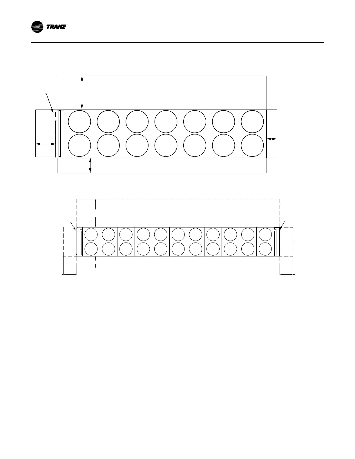
Service Clearance
Figure 1. Unit service clearance requirements — 150 to 330 ton units
36” (914.4mm)
40”
(1016
mm)
24”
(600.1mm)
Control
Panel
NO OBSTRUCTIONS ABOVE UNIT
TOP VIEW
See
note 1
85” (2160mm)
See note 3
Figure 2. Unit service clearance requirements — 375 to 550 ton units
85” (2160mm)
36” (914.4mm)
See note 3
40” (1016mm)
See notes
40”(1016mm)
See notes
Circuit 1
Circuit 2
Control
Panel
with TD7
User
Interface
Control
Panel
Notes:
1. A full 40” clearance is required in front of the
control panel(s). Must be measured from front
of panel, not end of unit base. Installer must
also follow NEC and local/state codes for
electrical clearance requirements.
2. Area above unit is required for operation,
maintenance, access panel and air flow. No
obstructions above unit.
3. Clearance of 85” on the side of the unit is
required for coil replacement. Preferred side for
coil replacement is shown (left side of the unit,
as facing control panel), however either side is
acceptable.
4. For obstructions or multiple units, refer to
Close-Spacing and Restricted Airflow
Situations, Ascend™ Chiller Models ACR and
ACS, Sintesis™ Chiller Model RTAF
Engineering Bulletin (AC-PRB001*-EN).
Dimensions and Weights

 Loading...


