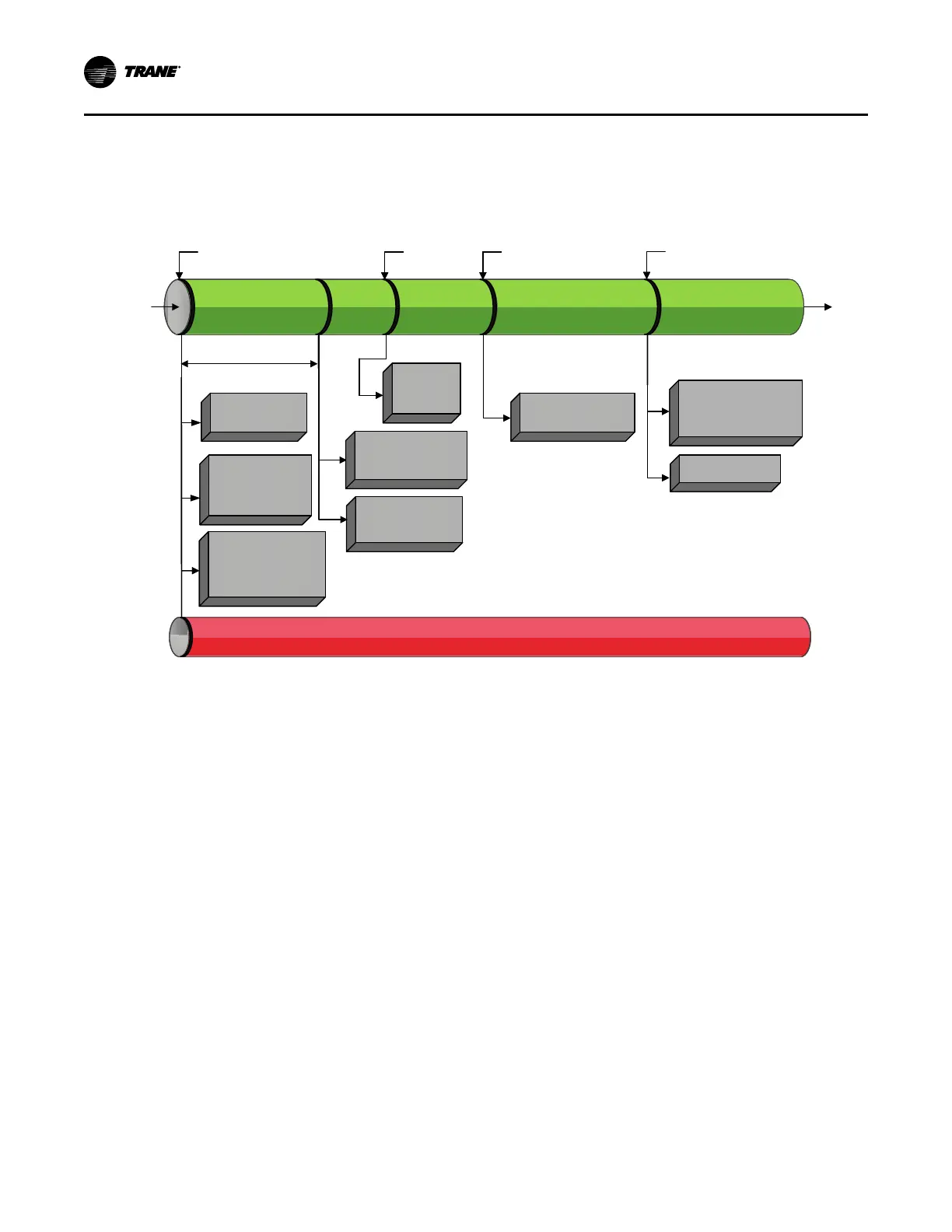
*Note: The decision to stage on or off another compressor is determined by
the Average Running Compressor Load Command, Water Temperature Error, and Time Since Last Stage
On a manifolded circuit, GP4 will be the first to start and last to stop; GP2 will not run by itself.
Compressors
Running
Chiller and Both Circuit
Modes are “Running”
De-Energize Oil
Heater(s) of
Energized Circuit(s)
Control Both Circuit
Condenser Fans for
Optimum Differential
Pressure,
ƒ(Cprsr Spd, OA Temp)
Enforce All Running Mode Diagnostics for ChillerEnforce All Running Mode Diagnostics for Chiller
Modulate
Compressor
for Limit
Control
Modulate Compressor
for
Capacity Control
RunningRunning RunningRunning
Exit
Limit Mode
Exit
Limit Mode
Enter
Limit Mode
Enter
Limit Mode
RunningRunning
Energize Maximum
Capacity Relay after the
Adjustable Filter Time
(0 to 1500 Seconds)
Continue
Running
(All
Cprsrs &
Max
Capacity
Maximum Capacity
Submode
RunningRunning
Running
Lag Circuit:
Running Limit
Running
Lag Circuit:
Running Limit
All Compressors Running
At or Near Max Capacity
(Unable to Achieve CWSP)
*Note: The decision to stage on or off another compressor is determined by
the Average Running Compressor Load Command, Water Temperature Error, and Time Since Last Stage
On a manifolded circuit, GP4 will be the first to start and last to stop; GP2 will not run by itself.
Compressors
Running
Chiller and Both Circuit
Modes are “Running”
De-Energize Oil
Heater(s) of
Energized Circuit(s)
Control Both Circuit
Condenser Fans for
Optimum Differential
Pressure,
ƒ(Cprsr Spd, OA Temp)
Enforce All Running Mode Diagnostics for Chiller
Modulate
Compressor
for Limit
Control
Modulate Compressor
for
Capacity Control
Running Running
Exit
Limit Mode
Enter
Limit Mode
Running
Energize Maximum
Capacity Relay after the
Adjustable Filter Time
(0 to 1500 Seconds)
Continue
Running
(All
Cprsrs &
Max
Capacity
Maximum Capacity
Submode
Running
Running
Lag Circuit:
Running Limit
All Compressors Running
At or Near Max Capacity
(Unable to Achieve CWSP)
Modulate
Compressor for
Capacity Control
Modulate EXV for
Pressure Control
Hold EXV Pre-position
Hold EXV pre-
position

 Loading...


