AC-SVX001A-EN
33
• Shutoff (isolation) valves.
• Thermometers.
• Clean-out tees.
• Balancing valve.
Drains
A 1/2” drain connection is located under outlet end of
evaporator waterbox for drainage during unit
servicing. A shutoff valve must be installed on drain
line.
Pressure Gauges
Install field-supplied pressure components as shown in
figure above. Locate pressure gauges or taps in a
straight run of pipe; avoid placement near elbows, etc.
Be sure to install the gauges at the same elevation on
each shell if the shells have opposite-end water
connections.
To read manifolded pressure gauges, open one valve
and close the other (depending upon the reading
desired). This eliminates errors resulting from
differently calibrated gauges installed at unmatched
elevations.
Pressure Relief Valves
NNOOTTIICCEE
EEvvaappoorraattoorr DDaammaaggee!!
FFaaiilluurree ttoo ffoollllooww iinnssttrruuccttiioonnss bbeellooww ccoouulldd ccaauussee
ddaammaaggee ttoo tthhee eevvaappoorraattoorr..
TToo pprreevveenntt eevvaappoorraattoorr ddaammaaggee,, iinnssttaallll pprreessssuurree
rreelliieeff vvaallvveess iinn tthhee eevvaappoorraattoorr wwaatteerr ssyysstteemm..
Install a water pressure relief valve in the evaporator
inlet piping between the evaporator and the inlet
shutoff valve, as shown in figure above. Water vessels
with close-coupled shutoff valves have a high potential
for hydrostatic pressure buildup on a water
temperature increase. Refer to applicable codes for
relief valve installation guidelines.
Evaporator Flow Switch
NNOOTTIICCEE
FFllooww SSwwiittcchh DDaammaaggee!!
IInnccoorrrreecctt vvoollttaaggee aapppplliiccaattiioonn ccoouulldd ccaauussee ddaammaaggee
ttoo tthhee ffllooww sswwiittcchh..
FFllooww sswwiittcchh iiss oonn aa 2244VV cciirrccuuiitt.. DDoo NNOOTT aappppllyy 112200VV
ttoo tthhee ffllooww sswwiittcchh..
The flow switch is factory-installed and programmed
based on the operating conditions submitted with the
order. The leaving evaporator temperature, fluid type
and fluid concentration affect the selected flow switch.
If the operating conditions on the job site change, the
flow switch may need to be replaced. Contact your
local Trane Sales office for more information.
The sensor head includes 3 LEDs, two yellow and one
green. Wait 15 seconds after power is applied to the
sensor before evaluating LEDs for flow status. When
wired correctly and flow is established, only the green
LED should be lit. Following are the LED indicators:
• Green ON, both yellow OFF — Flow
• Green and outside yellow ON — No Flow
• Center yellow ON continuously — Miswire
Factory installed jumper wire W11 must be removed if
using auxiliary contacts and/or additional proof of flow.
See schematics in AC-SVE001*-EN for more details.
NNOOTTIICCEE
EEqquuiippmmeenntt DDaammaaggee!!
IInnccoorrrreecctt wwiirriinngg ooff aauuxxiilliiaarryy ccoonnttaaccttss ccoouulldd ccaauussee
eeqquuiippmmeenntt ddaammaaggee..
SSeeee sscchheemmaattiiccss ffoorr pprrooppeerr wwiirriinngg..
If using auxiliary flow sensing, both yellow LEDs come
on initially when flow is stopped. The center yellow
LED will turn off after approximately 7 seconds. The
LED indicators are otherwise the same as indicated
above.
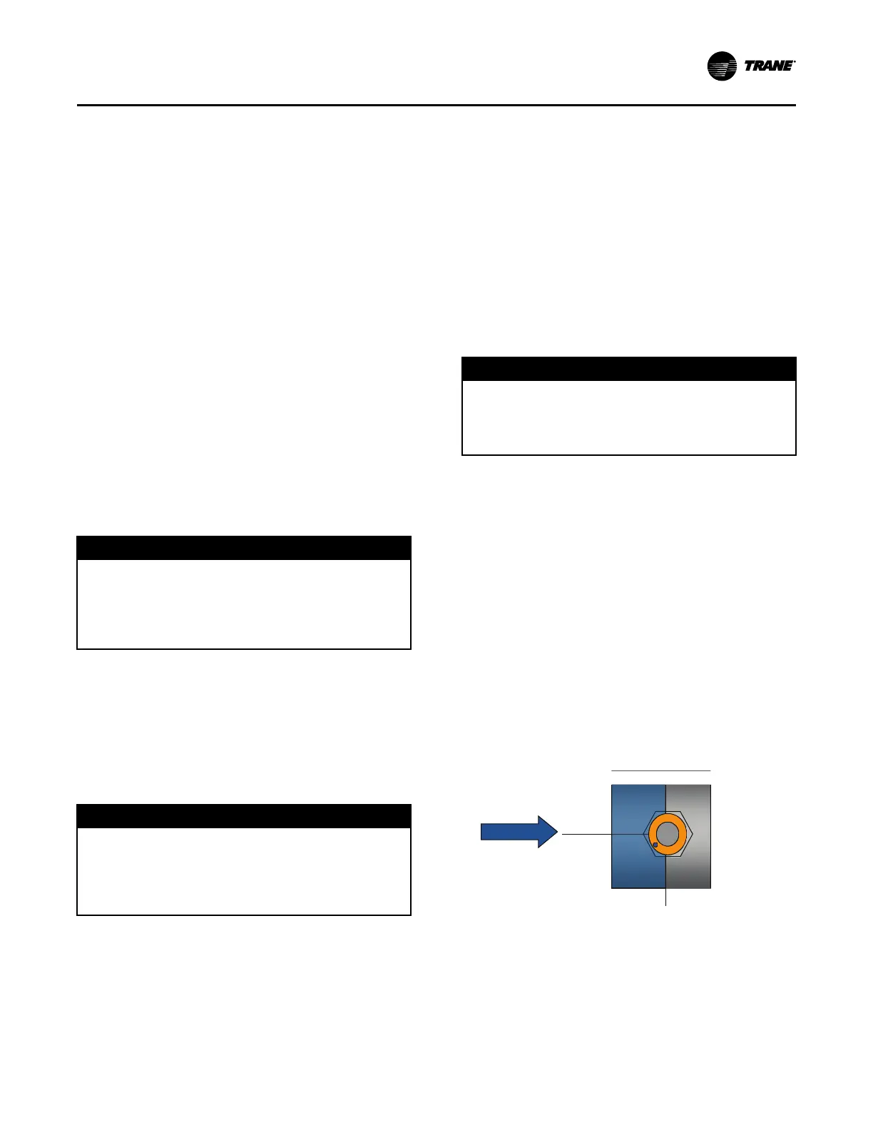
Indexing Flow Switch
To properly index the flow switch, the following
requirements must be met:
• The dot must be at a position no greater than 90° off
Index.
• The torque must be between 22 ft-lb minimum and
74 ft-lb maximum.
• A minimum distance of 5x pipe diameter must be
maintained between flow switch and any bends,
valves, changes in cross sections, etc.
Figure 16. Proper flow switch indexing

 Loading...