AC-SVX001A-EN
73
Running (Lag Compressor/Circuit Start
and Run)
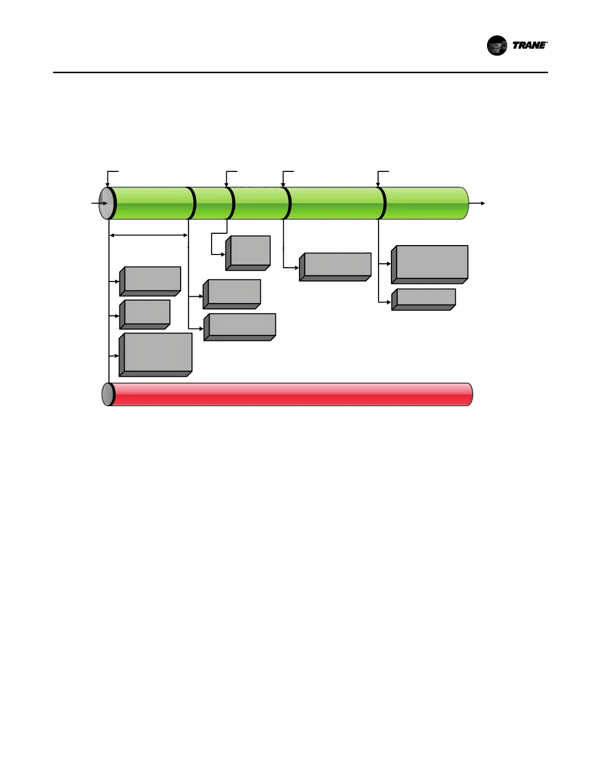
The following diagram shows a typical start and run
sequence for the lag compressor and its circuit.
Figure 55. Sequence of operation: running (lag compressor/circuit start and run)
*Note: The decision to stage on or off another com pressor is determ ined by
the Average Running Com pressor Load Command, W ater Tem perature Error, and Time Since Last Stage
H o ld E X V P re -p o s ition
(10 S eco n d s )
B oth
C om p resso rs
R un n in g
C hille r and B o th C ircuit
M o des a re “ R u n n in g ”
H o ld E X V o f L a g
C irc u it a t p re -
positio n for 1 0 s ec
D e-energiz e
O il H eate rs
O f Lag C irc u it
C o n tro l B oth C ircuit
C o n d ense r Fan s for
O p tim u m Differential
P re ssu re,
ƒ(C p rs r S p d , O A T em p )
E n fo rc e A ll R u n n in g M od e D iag n o s tics for C h iller, L e a d C o m p ressor an d its C ircuit
M o d u la te E X V fo r
Liquid Leve l &
P re ssu re C o n tro l
M o d u la te
C o m p re ssor
S peed fo r
Lim it C o n tro l
M o d u la te C o m pre s sor
S peed fo r
C apacity C o n tro l
M o d u la te C o m pre s sor
S peed fo r
C apacity C o n tro l
E x it
Lim it M o d e
E n te r
Lim it M o d e
R u n n in g
E nergize M axim u m
C apacity R elay a fte r th e
A d ju stab le F ilte r Tim e
(0 to 6 0 0 S e conds)
C on tinu e
R un n in g
(B o th
C om p rsrs
& M a x
C apa c ity
M a x im u m C a p a city
S ubm ode
R u n n in g
Lag C ircuit:
R un n in g L im it
B oth C o m presso rs R u nn ing
A t o r N ear M ax Sp e ed
(U n a b le to A chie v e C W SP )
SSttaarrtt--uupp aanndd SShhuuttddoowwnn

 Loading...