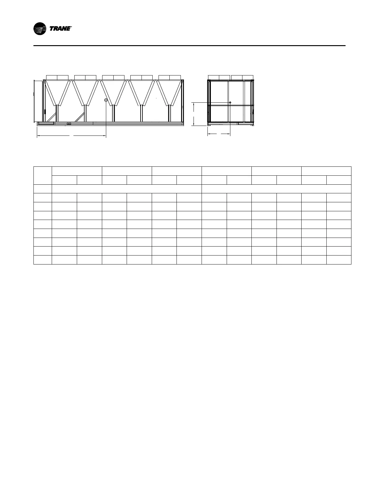
Table 6. Center of gravity dimensions
Unit
Size
CGx
CGy
CGz CGx
CGy
CGz
in
mm
in
mm
in
mm
in
mm
in
mm
in
mm
Standard Length Unit Extended Length Unit
150 93.9 2384 44.2 1122 44.2 1124 128.2 3255 44.0 1118 43.3 1100
165 105.8 2686 44.2 1122 45.9 1166 139.1 3532 44.2 1124 44.9 1142
180 106.0 2691 44.5 1131 45.6 1159 139.6 3545 44.5 1129 44.7 1135
200 114.1 2898 44.1 1121 47.2 1199 147.2 3738 44.2 1124 46.3 1175
225 115.8 2941 44.1 1120 45.2 1148 148.8 3780 44.2 1122 44.4 1129
250 115.1 2924 44.1 1120 45.6 1158 149.0 3785 44.1 1121 44.8 1139
275 127.7 3242 44.0 1117 46.1 1172 162.3 4122 44.2 1122 45.4 1153
300 139.5 3544 44.0 1116 47.1 1197 174.3 4427 43.8 1113 46.4 1178
Isolation and Sound Emission
The most effective form of isolation is to locate the unit
away from any sound sensitive area. Structurally
transmitted sound can be reduced by elastomeric
vibration eliminators. Spring isolators are not
recommended. Consult an acoustical engineer in
critical sound applications.
For maximum isolation effect, isolate water lines and
electrical conduit. Wall sleeves and rubber isolated
piping hangers can be used to reduce the sound
transmitted through water piping. To reduce the sound
transmitted through electrical conduit, use flexible
electrical conduit.
State and local codes on sound emissions should
always be considered. Since the environment in which
a sound source is located affects sound pressure, unit
placement must be carefully evaluated. Sound power
levels for Stealth chillers are available on request.
Unit Isolation and Leveling
For additional reduction of sound and vibration, install
the optional elastomeric isolators.
Construct an isolated concrete pad for the unit or
provide concrete footings at the unit mounting points.
Mount the unit directly to the concrete pads or
footings.
Level the unit using the base rail as a reference. The
unit must be level within 1/4” (6.4 mm) over the entire
length and width. Use shims as necessary to level the
unit.
Elastomeric Isolators
NNoottee:: See unit submittal, or tables in this section, for
point weights, isolator locations and isolator
selections.
1. Secure the isolators to the mounting surface using
the mounting slots in the isolator base plate. Do not
fully tighten the isolator mounting bolts at this time.
2. Align the mounting holes in the base of the unit
with the threaded positioning pins on the top of the
isolators.
3. Lower the unit onto the isolators and secure the
isolator to the unit with a nut.
4. Level the unit carefully. Fully tighten the isolator
mounting bolts.
IInnssttaallllaattiioonn MMeecchhaanniiccaall

 Loading...