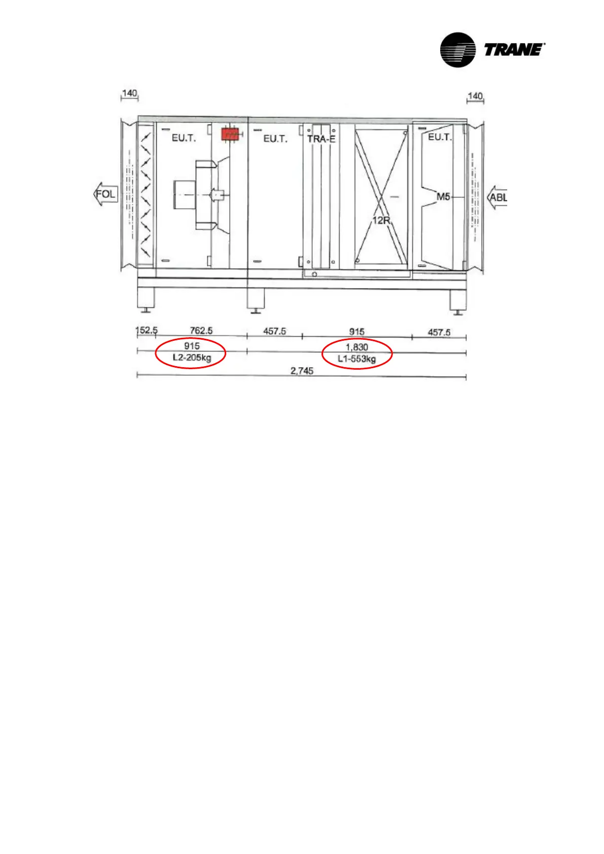
Figure 18: A monobloc, which consists of the two sections L1 and L2
3.4.2 Lifting of monoblocs
- Monoblocs are generally delivered with a perforated counter-frame – hole diameter 50 mm –
for inserting suitable tubes/rods, where the unit is lifted, see Figure 19 and Figure 20.
- The tubes/rods are not included in the delivery scope, but have to be provided by the company,
which is responsible for the lifting operation.
- Two, three or more holes per side of the monobloc are available according to the length and
weight of the unit. As a consequence, two or more tubes/rods can be used.
- The determination of the number and the dimensions of the tubes/rods and the load carrying
equipment are the responsibility of the performing company.
- We recommend varifying the suitability of the selected tubes/rods by a structural engineer.
- The force effect has to take place uniformly across all tubes/rods.
- The load carrying equipment must be secured against slipping off, e.g. see Figure 21.