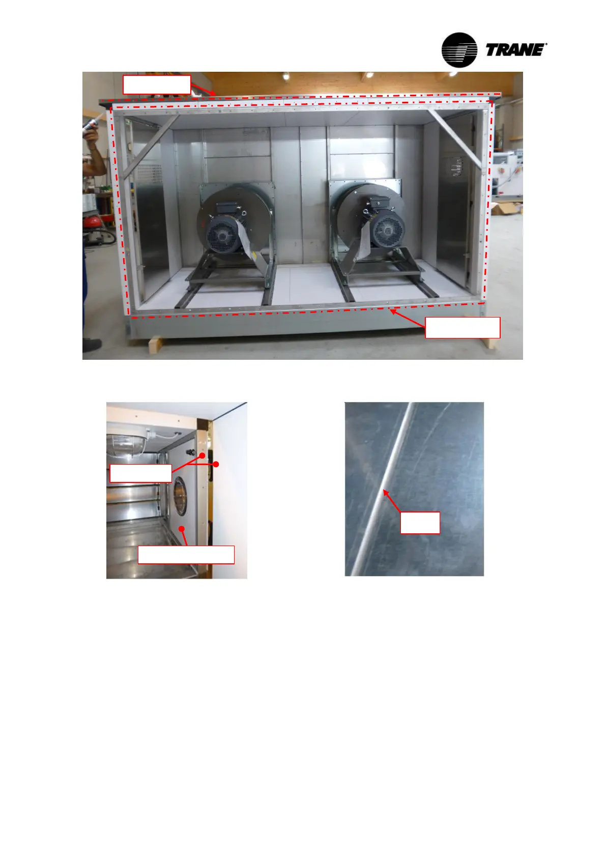
Figure 65: Applying the sealing agent on the frontal joints
Figure 66: Unit separation acces-
sible via door
Figure 67: Sealing the section
connection (joint) with the sealing
agent
5.1.6 Cable gland
For the connection of engines, pumps, electric heaters, sensors, etc., TRANE loosely supplies ma-
terial for cable glands (Figure 71), which must be installed properly. The following procedure is
recommended:
1. Drilling through unit casing (at right angles to the surface).
2. Enlarge drillings on external panel and internal panel according to Table 3 (by using a step drill
– see Figure 68).