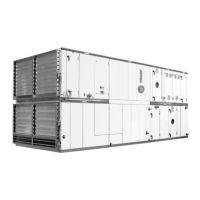
Figure 50: Self-tapping screw ø6,3 x 22
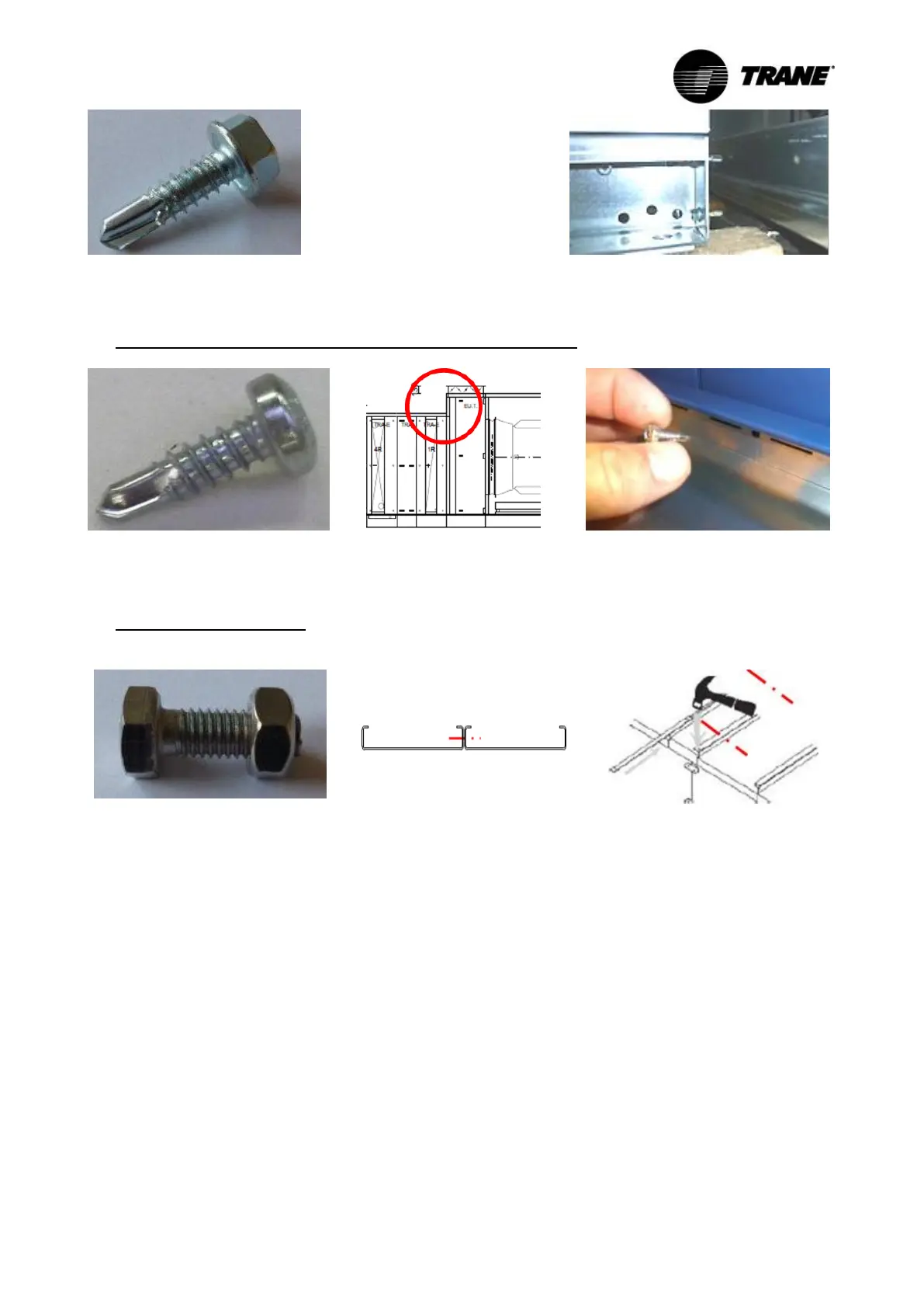
Figure 51: Application of self-tapping screws
- Connection of internal panels with the front side of the casing
Figure 52: Self-tapping screw TORX
25 ø4,8 x 16
Figure 53: Joint on the AHU draw-
ing
Figure 54: Joint at the AHU
- Connection of roof plates
Screw spacing: minimum 305 mm
Figure 55: Hexagon bolt with nut
(stainless steel) M6x16
Figure 56: Connection of roof plates
Figure 57: Mounting of the sliding bar
5.1.4 Assembly of delivery sections
Bring the delivery sections in the exact mounting position and push them together as near as pos-
sible. The screw holes on the flanges have to lie opposite now.
Moving delivery sections together
The precisely aligned and parallel flanges are connected with the enclosed screws. Initially, all
screws are only loosely screwed as follows:
- In the base frame profiles (Figure 58 left).
- If accessible, in the connection angles located in the upper corners of the unit (Figure 58 bot-
tom center).
- If accessible, in the circumferential connection frame (Figure 58 top center).
- In the panels (Figure 58 right).
- For roof units in the roof flange.