Installation
24 SO-SVN037A-EN
LTE Modem Installation
Modem part is MOD03184, MODULE; CELLULABLE USB 2.9
METER CABLE. Refer to provided literature for setup and
operation details.
1. Drill a 1.36 inch holes on the top of polycarbonate box,
securely fasten the LTE modem by gasket and nut which
provided by modem.
2. Connect LTE modem to Symbio800 by USB cable which
provide by module, plug USB MICRO-B side to bottom of
LTE modem and USB-A side to any one of the four USB
ports under the Symbio800 controller.
Communication Device Mounting
These devices are intended to be mounted on polycarbonate
boxes. There are two installation approaches:
• Each device is mounted independently on a small box
(0185-0426-0100).
• Multiple devices are mounted on a large box (0185-0427-
0100).
All devices connect Symbio 800 by standard USB or Modbus
cable. For installation, standard application need to field drill an
1.09-inch hole on side of box for a snap bushing. This bush can
be replaced as field straight connector and conduit (3/4 inch
size) as NEMA 4 applications.
The boxes have magnets for flexible attachment to the Symbio
panel.
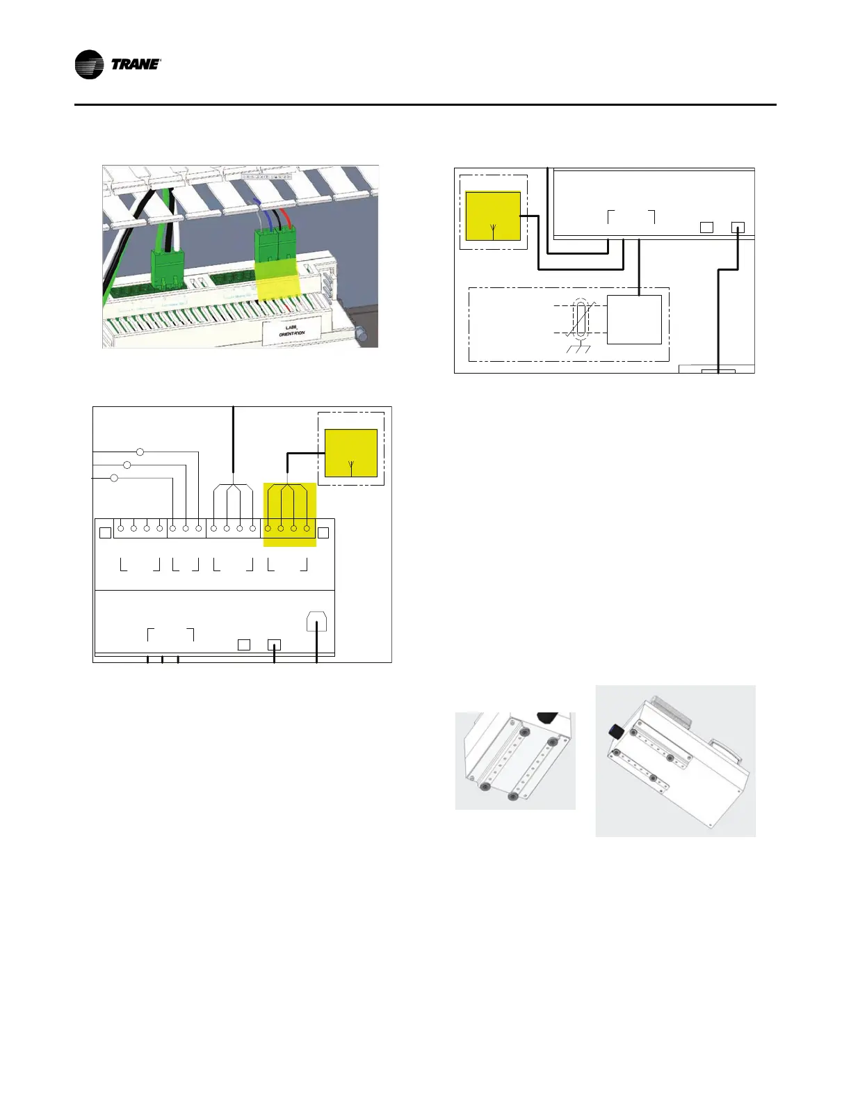
Figure 39. Air-Fi terminal
Figure 40. Air-Fi wiring, ref. 50712792
+24
G
-
+
IMC
RED
BLK
GRN
WHT
RED
BLK
BLU
GRY
VDC
+24
G
-
+
MACHINEBUS
VDC
P3
-
+
BACKNET
P1
-
+
-
+
MODBUS
P2
G
AIR-FI
4K48
INTERFACE
OPTIONAL
IMC
B
IMC
A
1A22 SYMBIO 800 UNIT CONTROLLER
SERVICE
ETHERNET
12
USB
1324
TOOL
WHT
GRN
BLK
1X3-1
1X3-2
1X3-3
BLK
BLU
RED
Figure 41. LTE modem wiring
Figure 42. Polycarbonate box with magnets
1A22 SYMBIO 800 UNIT CONTROLLER
ETHERNET
12
USB
12 4
LON
1K47
INTERFACE
TRACER
OPTIONAL
COMMUNICATIONS
LT E
4Y2
MODEM
OPTIONAL
3
 Loading...